This procedure includes enough checks to be
followed as a "Pre-AO Run" check list, after a long period without observation
or when engineering work has been done in GRACE.
On a normal day during an AO observing run it is not expected that the Duty Engineer performs the whole list of readiness
checks (for example the DE usually won't have to flatten the Deformable
Mirror). But as the "daily" and "readiness"
checklists share many actions in common,
it was decided to write only one procedure. Simply, a note is written any
time an action is specific to the complete readiness checklist or instead
specific to the reduced daily checklist.
List of abreviations (or names)
-
DM:
Deformable Mirror
-
SG:
Strain Gauge (for the control of the DM segments)
-
FSM:
Fast Steering Mirror
-
NCU:
Nasmyth Calibration Unit (slide with pinholes, calibration lamps and
AG3 camera)
-
OAP2:
Off-Axis Paraboloid number 2
-
OAP1:
Off-Axis Paraboloid number 1, it’s in fact the FSM
-
WFS:
Wave Front Sensor
-
OMC:
Opto Mechanical Chassis (associated mostly to the WFS)
-
USP:
Universal Science Port, to which OASIS is attached. By extension,
mechanisms on the optical bench.
-
FISBA:
brand of the interferometer used for mirror flattening.
qSummary
of NAOMI start-up checks
- In GRACE
- Inspection of the Light
Path
- Temperature and Humidity
conditions
- Inspection of electronics
racks
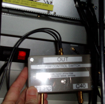
- Switching from L3 (Tip-Tilt) to CCD39
- In the WHT Control Room
Environment
-
Temperature and Humidity
are seen from the display either below the Met display in the Control
Room or in Grace Electronic Room. Humidity should be maintained above
30% (too low it makes the piezo-electric SG unstable). Steep gradients
in T or %RH are especially bad for DM stability.
-
Check in Grace if the de-humidifier
tank needs to be emptied
-
Only during an AO run Depending on conditions
start-up the humidifier (only a few hours autonomy with full tank)
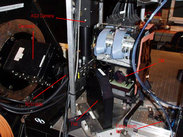
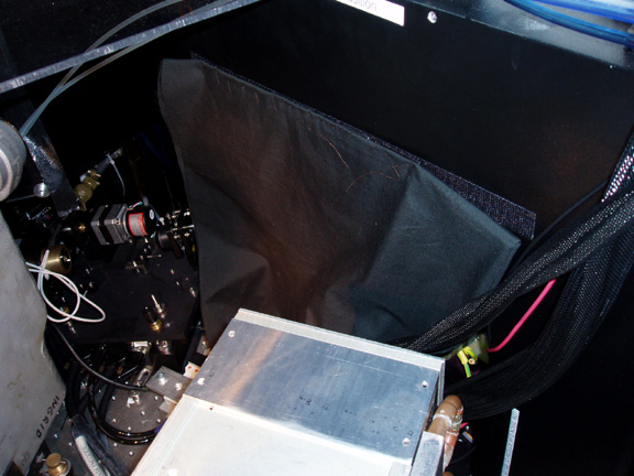
Inspection of the light path
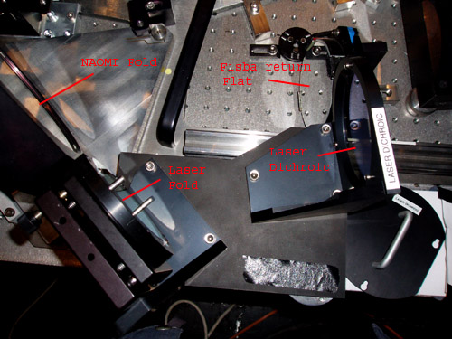
View of the new components: Laser Dichroic
and Fold. Only the dichroic is in the optical path for science.
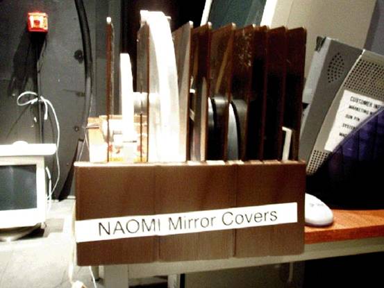
Where to store the mirror covers
- Readiness checks only Especially
if engineering work has been going on, check if nothing obviously obscures
the light path (forgotten tools, mask). More subtle obscuration (e.g.
a mask in front of the detector!) will need imaging with WFS to reveal
itself.
- Readiness checks only
Check which pinhole is at the Simplex position on the NCU: the 2µm
pinhole will be needed for a good simplexing process. If it needs to
be changed, the whole series of pinholes is kept in a plastic box on the
table next to the cover rack. It is simply screwed into its position.
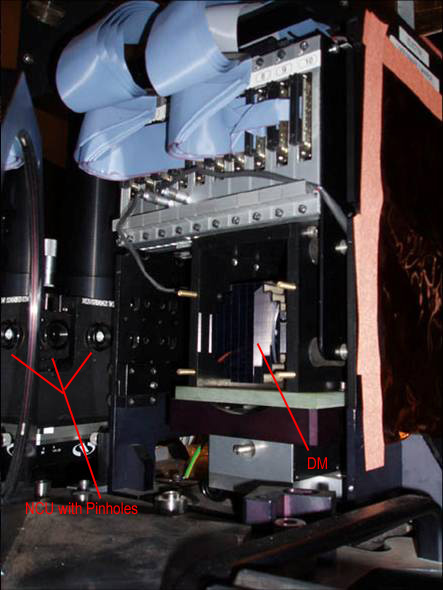 close up of the NCU showing pinholes,
and the DM
close up of the NCU showing pinholes,
and the DM
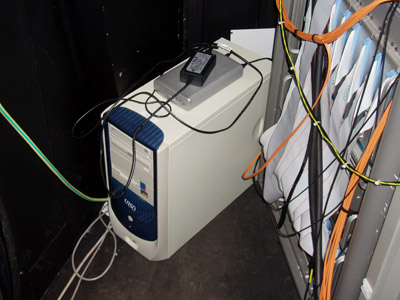
Electronics
- The camera configuration file at first has to be edited
on Taurus, but if it’s not the first day of an AO run and you don’t want
to interfere with the main instrument, the AO observing system can be
brought up on standalone from lpss94.
-
In any case, obssys has to be started
on the das machines for the following detectors: AG3 (the acquisition
camera), AG7 (the simplex camera), the instrument cameras INGRID and/or
MITLL3 (for OASIS), so some access is needed on Taurus at least to edit
the config file and startobssys in the orange das windows. For DE checks: see the
observing schedule or ask the support astronomer to know which instrument
camera will be used at night.
- Readiness checks only
To work from lpss94:
- telnet to lpss94 (for example from an xterm in the
second working space of the right AO Display scree), login as whtobs
- Type set instrument_config_file = /wht/var/instrument.cfg.ao
- Type obssys, answer 1, 1, then startobssys. In this
way, the AO servers (like oasisserver) are started, as well as all
observing guis like the AO mimic, NAOMI Observer gui,…
- DE checks only
Start the observing system on Taurus with
at least one instrument camera (Ingrid or OASIS) in the configuration
file, because in this way all the servers start automatically (like
oasisserver).
- Start the camera sanity checks by taking bias runs for each
camera and examine the noise level with Iraf
Back to menu
AODISPLAY is a pc which allows to emmulate a unix session (via Exceed)
either to Navis or lpss42. Use the login name naomi.
The left screen is an 8-bit display and reserved for topgui; the right
screen is a 24 bit display and allows to launch more complex (and modern)
mimics or gui's. DE checks only
If the AO system has been in use on the previous night, it shouldn't
be necessary to log on again.
From AODISPLAY right screen:
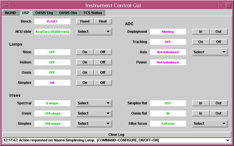
- From oasisgui USP page float the
bench (takes 5min to stabilise); move the NCU to simplex position.
Disregard the ADC (not commissioned)
-
If Ingrid or OASIS is going
to be used try moving mechanisms from Ingrid, OASIS pages. Some
(enlarger or imager wheels on OASIS) might require more than one
attempt. It’s very unusual when none of the mechanisms on the same tab
(USP, Ingrid or OASIS) can be be initialised. In that case the VMS rack
in GRACE controlling these mechanisms needs to be rebooted, then all
mechanisms initialised from oasisgui.
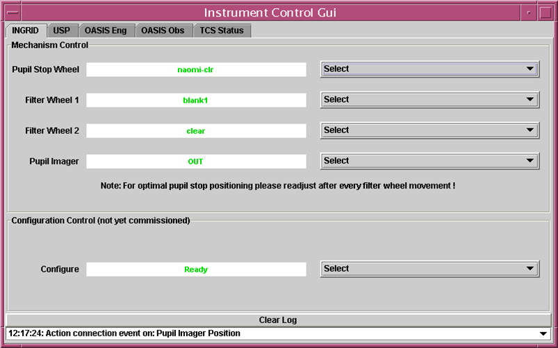
oasisgui INGRID page
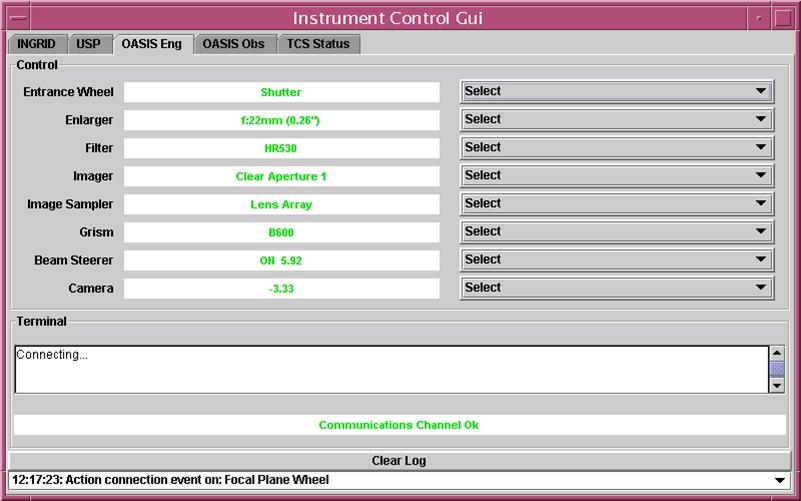
oasisgui OASIS Engineering page
From AODISPLAY left screen:
-
At the prompt in a console or xterm (lpss42 or
navis) type restart or NaomiRestart then topgui &
. Note for
DE checks: If TopGui was still running from the night before, restart
will kill the process.
-
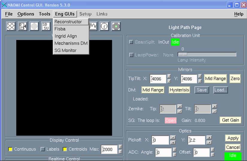
The left half of Topgui is
static, the right page gives access
to SDSU control, C40, Mirror Control, Light Path, etc either from the icons or from the Tools
menu.
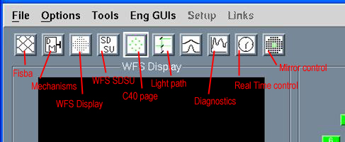
TopGui icons and Tools menu
-
From the C40 page check if all 16 processors are in green. Left ring
is for WFS, right for Strain Gauges (ie DM control). The SG icon
is pink which means the loop is open, that’s normal. NaomiRestart usually
clears most processor problems. If not: when a second restart doesn’t
help see the “special case” recipe in the green Naomi Software folder,
at the tab Trouble (hand written in the margin)
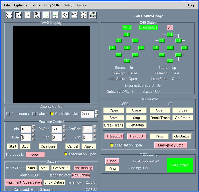
TopGui C40 Control page
- In C40 Control under WFS click on Start to get WFS
into framing mode and in the Display Control click on Continuous
-
Check noise level on the WFS,
either visually (with Max level
in the Display Controlset at 100,
no diamond structure is visible on
the image) or more precisely from the WFS Display page,
with a Grab, Save as Fits and then
display of the file on iraf, using imexam. An rms value of 7 to 10 is normal. To run
Iraf, you will need to start an xgterm, in it from the home directory type
ds9& then cl. The grabbed files for the WFS are
kept in the directory /opt/Electra-save-dir/Grabs/WFS
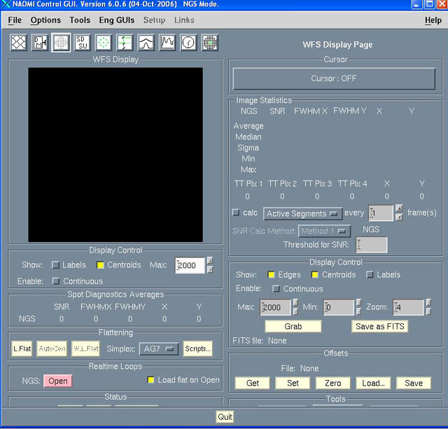
WFS Display page, from which to Grab
an image of the WFS
-
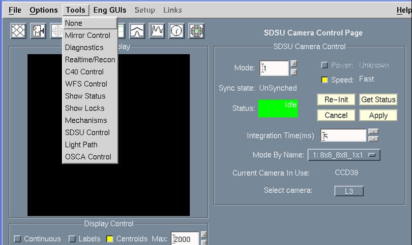
Sanity check for the WFS SDSU:
try changing to Mode 10 (while the WFS is framing, but not in continuous
display because this would give a Timeout error) then switch back to Mode 1. If Status turns to Error,
power cycle the SDSU power supply and VME crate (centre electronic
rack, bottom).
-
After an SDSU power cycle
or if it gives repeated Timout errors the WFS needs a Re-Init from TopGui
WFS control (SDSU) page
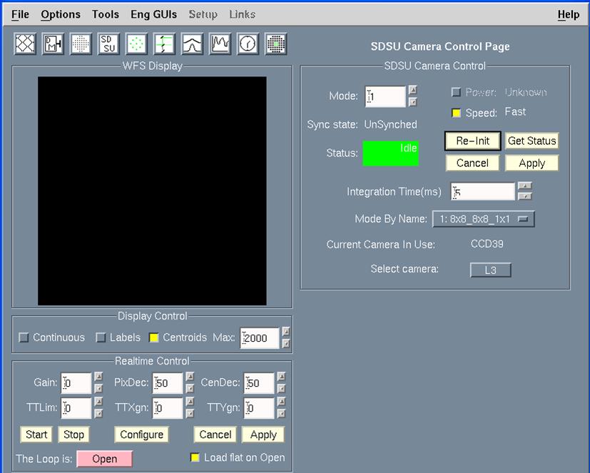
SDSU Camera Control page, from which
to Re-Init the WFS SDSU
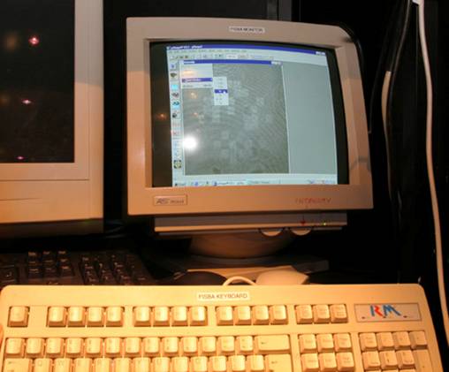
Switch on the Fisba Monitor, on channel A
Note: a display of the Fisba screen can also be started
from a web browser: http://gracecamserver1 and select "DM"
as the source.
Back on AODISPLAY
- Readiness checks only Initialise the pick-off probe and other mechanisms
for the WFS:
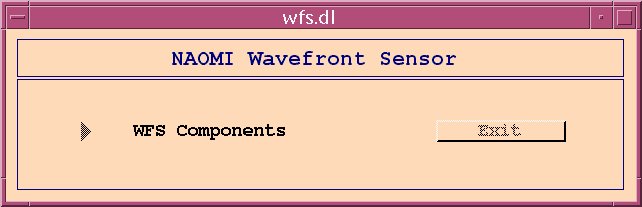
from TopGui’s EngGuis – Mechanisms DM bring up 3 cascaded windows: NAOMI Mechanism control
mechs.dl, right-click on NAOMI systems to start Wavefront
Sensor wfs.dl, right-click on WFS Components
to start Pickoff Mechanisms pickoff.dl.
Click Init, Start, wait for the Idle status, and click Index,
Start. It takes a few minutes to initialise, and this will
leave the pick-off probe at (X,Y) = (5.32,3.31). From TopGui send
it back to 0, 0.
Note: right-clicking
on the second brown window allows access to other mechanisms: WFS Filter
wheel and WFS ADC; this is the way to initialise them.
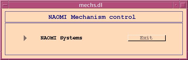
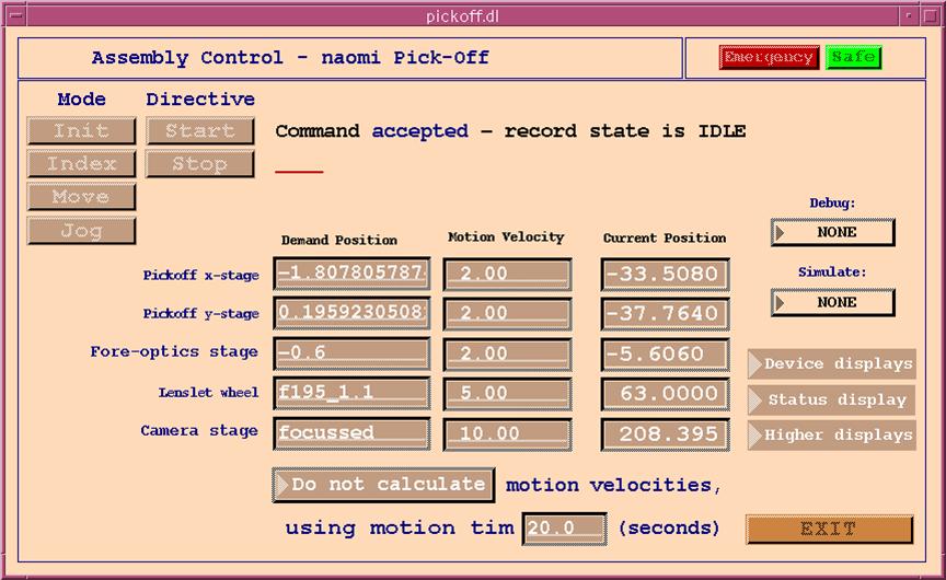
How to intialise the Pickoff and
related mechanisms from the engineering gui's
-
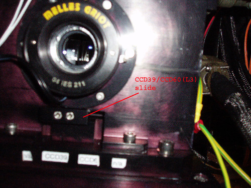
DE checks essentially
If during
the previous night the L3 WFS has been used (with OASIS in Tip-Tilt mode),
then the camera stage position has to be adjusted so that the Shack-Hartmann
spots are focussed on the CCD39 WFS. Usually
the position to focus on L3 is around 172mm and for CCD39 it's around 210mm.
You need to open the Pickoff engineering gui as described above,
then type focussed in the Camera stage, press Enter then
Move and Go.
- Check on TopGui if the SG (Strain Gauge)
gain is 0.8, otherwise type SG SetGain 0.8
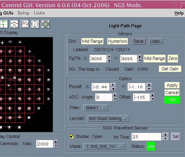
- From the Light Path page load
the latest DM flat (usually from last night). On the Fisba
monitor with the interferogram, the DM segments
will still show lots of fringes.
-
From the C40 page close the
SG loop.
DE checks only If temperature and humidity conditions have not changed
dramatically since the end of the night, the flat should still be good
enough (on the Fisba display all segments visible and uniformly lit,
no fringes or only a couple of fringes visible). If not, a laser (Fisba) flat is needed;
see the procedure below.
Readiness checks only
Probably fringes will be lost (completely blurred) on several segments.
After a long period of inactivity (> week) try out several previous
flats if needed. For Fisba laser flattening process to work fine, an acceptable
starting point is when interference fringes are seen on each DM segment.
-
From oasisgui USP page switch
on the simplex light, Iris at -150
-
From TopGui Light Path page
open (if it's not already ticked as open) the WFS Shutter.
-
Send the pick-off probe to
0,0.
-
Spots should be visible on the WFS Display. Otherwise (and if the pickoff is at the right position,
NCU light is on, shutter open) something has been left on the light
path! You can also suspect the CCD60 / CCD39 switch below the WFS to
be in the wrong position.
-
Centre approximately the spots on the DM grid (a segment
is 2arcsec wide) by entering values in the Pickoff X and Y
boxes and clicking Apply,
then click on
Autocentre
from the General Scripts gui
to recentre precisely.
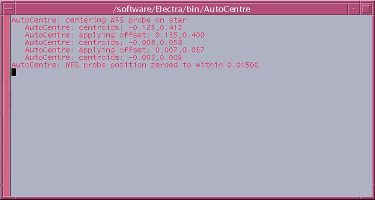
General Scripts gui, for AutoCentre,
and result of the AutoCentre. To close that pop-up window, just
locate the mouse cursor in it and press Enter
- Readiness checks only
As a sanity check, from TopGui try moving the FSM in X and Y, from
Light Path Page: Mid range is for 4096 adc; go to 5192, 3072, you should
see the spots move to the corner of a WFS cell if they were centered (1
arcsec = ½ cell). Then Midrange (not Zero!)
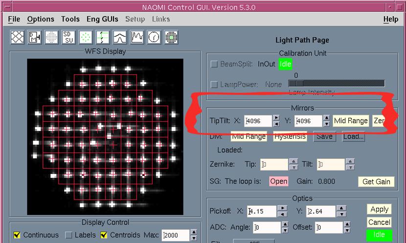 Control of the FSM (Tip Tilt mirror)
Laser (Fisba) Flattening of the DM (Readiness checks only)
- Go to the air conditionning console (upper left corner
above the TO console, next to the met station) and set Fan speed to
20% with the “knobs” menu
-
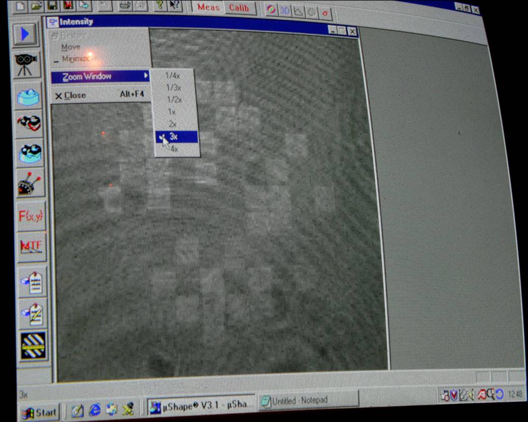
From TopGui Engineering Menu launch FISBA. Two pop-up
windows appear; one is for controlling the interferometer and launch
the flattening process, the other is a display of the interferogram
like the one on the monitor above. At first the display is black; click
on One Shot to populate the display. The normal Setup is
with X gain=0.5, Y gain=0.5 and Z gain=0 which means the laser flattening
algorithm does not move the segments in piston.
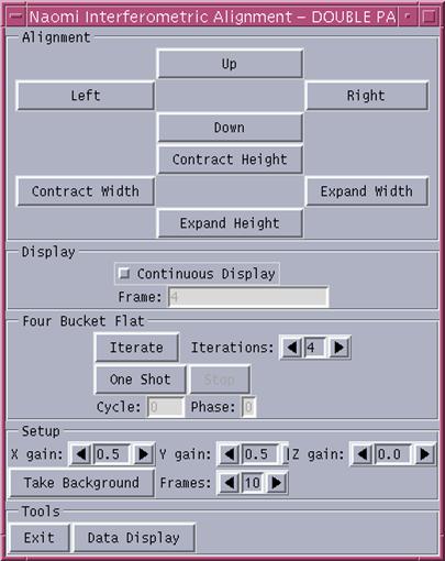
Fisba interferometer control window
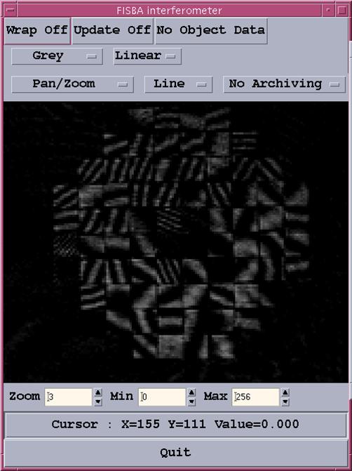
Interferometer display
- If not all DM elements are not visible (i.e. Fringes are
completely blurred on some segments) when the SG loop has been closed
on one of the latest flats in the list then it is necessary to tweak these
segments manually from TopGui Mirror Control page.
For this, select X -Y-Piston then click on any segment (which
turns in blue) and play with the arrows (only in X and Y; it's not
the purpose of the laser flattening to act on piston, this will be done
later by the White Light flatenning). If the segment turns to red when you
select it, a limit in X ,Y or piston has been reached.Set all 3 values
to 0 and try moving the segment again.
It often helps to look for the spot on the WFS Display window
in TopGui when you move a segment; then when the spot is roughly in its
red box corresponding to the DM segment, look at the Fisba display
and see how to get fewer fringes. A good starting point for the automatic
algorithm to work is when there are no more than 3 to 4 fringes in
each segment.
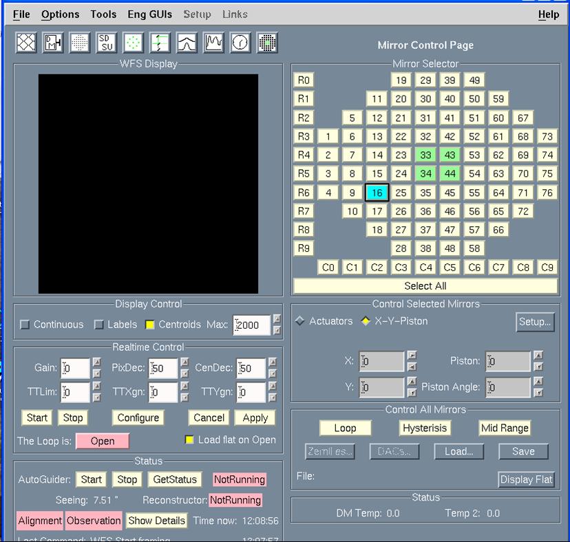
Mirror control page to move the segments
one by one in tip, tilt or piston
- To start the laser flattening automatic process, click
on Iterate in the interferometer control window.
- Two counters: Cycle and Phase are decrementing
down to 0 and the algorithm stops. A pop-up appears to remind us to turn
up the air conditioning fan speed. It's not critical to do that straight
away as other laser flats can be needed even after a White Light Flat
or a Simplex, but don't forget that temperature shouldn't be allowed to
change too much around the DM during the whole check-up procedure.
- Save this flat from TopGui Light Path page by clicking Save
button at the DM line (under Mirrors).
- All DM elements should be uniformly lit (all black or
white, fringes disappear). It can happen (especially if the previous
flat dates back to weeks ago) that one or several segments are lost
during the Fisba process. Then tweak them again by hand, save as a flat
and do another laser flat (and save it).
When the laser flat is good, all segments on the DM are parallel
but maybe not in the same plane. This will be corrected by the following
process, White Light Flattening.
Back to menu
White light flattening of the DM
(Readiness checks only)
- Switch on Simplex light, Iris = -150
- Check that the dichroic used is the 50/50 (important to have a broad
spectral range)
- Set WFS Integration Time to 25ms or 50ms
- Spots have to be bright enough for the algorithm to converge
- From the General Scripts window do an Autocentre
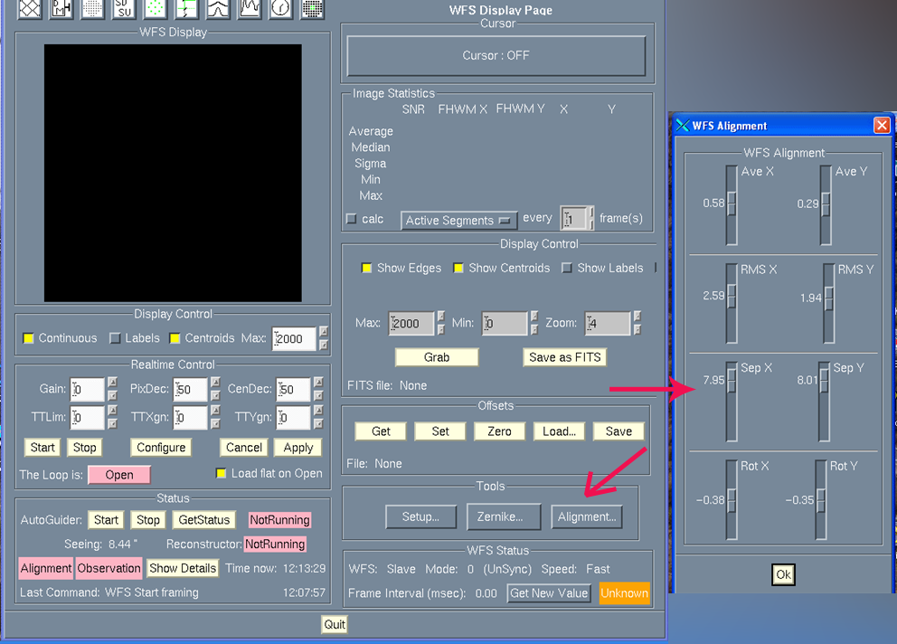
- Check focus of the WFS; the spots separation has to be
close to 8 pixels.To do this, go to TopGui WFS Control page (3rd button
from the left, or from the Tools menu) and click on the Alignment
tool. A new window appears, check separations: Sep X and Sep Y
which should be very close to 8 (or symetric around 8).
If necessary, adjust the WFS fore-optics focus by a few tenths
of millimeter from the EPICS guis. In the exemple below, the position
was shifted to -0.6mm (the nominal "focussed" position would be 0).
To adjust the Fore-optics stage position, place the cursor in
the Demand Position window, type the value, press Enter so
the value is in white, then successively press the buttons Move
and Start. I won't move if you don't click Start. Note
that Demand Position and Current Position are not
necessarily in the same units (it's a mystery).
- Type AutoWhite from Navis prompt
- Answer 0 (leave alone) to the question about Integration
Time
- The process takes more than 5 min; the X-shifted and Y-shifted
lenslet are successively used
- Note the result: we can consider the algorithm has given
a satisfactory result if:
- There are more than 120 measurements
- X and Y gradients are less than 200 in absolute value
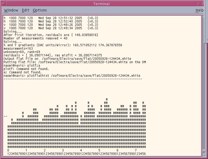
In the screen capture above, the number of measurements is 163,
and the X , Y gradients are a bit high, but acceptable. Note that a
new DM flat is automatically saved and its name is the same as the previous
laser flat, with a suffix
.white appended. This is why it's extremely
important to
save a laser flat just before doing a white light
flat; otherwise the coefficients found by the white light flat algorithm
will be applied to the latest laser flat in the directory (which is maybe
a week old) and the mirror flatness will be ruined! If it happens you
need then to start again by a laser flat.
- As shown above, the profile of the DM can be examined with
the command plotflathist (followed by the absolute name of
the flat file).
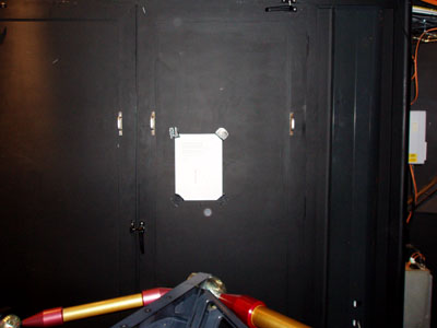
- For specialists: If Gradients are high, take out a global
tip (X) or tilt (Y) with AddZernike tip –(gradient/100) then the Fisba
return flat will need adjusting in Grace, followed by a new sequence
Laser/White light flats.
- After Laser Flat and White light Flat, don’t forget to
restore air flow to >80% in Grace, otherwise there will be a temperature
drift in Grace in the optics room.
Back to menu
Perform a Simplex to optimise image quality (Readiness checks only)
- Fix the bench and wait a few minutes before air completely
evacuates.
- If the simplex has to be done on INGRID, do the detector sanity checks first and leave the
instrument configuration ready for simplex (J, H or K bands).
- Start the simplex control window using either AG7, for
visible light (if OASIS will be used), or Ingrid for infrared. This is
done either by typing in a Xterm window mirroralign --camera AG7
(or -- camera INGRID) or from TopGui on the left side under the
black WFS display window, in the Flattening line, at Simplex click
to select the camera. Two new windows appear: one for the display and one
for the control.
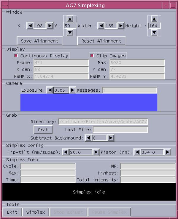 Simplex control window (here with AG7)
-
From the control window you can turn on/off the image
grabbing mode (check/uncheck Continuous Display), modify the size
and position of the display window (X and Y are the pixel coordinated
of the upper left pixel), change the camera integration time (Exposure).
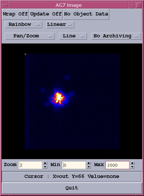 Simplex image display
- To simplex with Ingrid, take out OASIS and Simplex
mirrors (from USP tab on oasisgui),otherwise (simplexing with AG7) you
need both mirrors in.
- Use the 50/50 dichroic to simplex with AG7, and the IR dichroic
to simplex with Ingrid.
- Turn on the Continuous Display. The window position is the
one that was entered by the previous user, so normally the image of the
light source should be visible. If it's not there, you can display the
whole CCD and look for the spot coordinates, by unchecking Clip Images.
Then place the cursor on the spot, its coordinates are shown below the
display.
- Before starting the simplex algorithm, reduce the window
size to 30x30 pixels and recenter the image. If the window is too large
the simplex algorithm has too much information to process and takes longer.
- When simplexing with AG7, adjust the Filter Focus position
from oasisgui USP page (there is a simplex position at 2.20mm but
lately it seems better focused at 3.0mm). If the image is defocussed the
simplex algorihm will try to correct this by adding a focus term on the
DM.
- Adjust the Simplex lamp Iris from oasisgui USP page and
the camera integration time so that the maximum intensity (in the Max:
box under Clip Images) is between 10000 and 20000. It has
to be bright enough at the beginning, but not too much to avoid saturation
as the simplex converges. Typically set the simplex iris at -250 to -290,
and 0.015s to 0.030s for the camera exposure time.
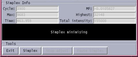
- Click on Simplex
- Monitor the Merit Function (MF): image is considered good
when MF < -0.015 (with AG7) or MF < -0.03 (with Ingrid)
- Usually image starts improving after 800 to 1000 cycles.
- If after 2000 cycles MF doesn’t improve, stop simplex
then start again: the algorithm may be stuck in a local minimum
- When the MF is satisfactory, stop the simplex algorithm
by clicking the Stop adjust button.
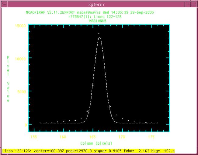
- Check the image quality: disable
Continuous Display in the simplex control window, then from Taurus take an image: run AG7 0.1
- Display the .fits file with
Iraf, use imexam j and k commands, or r
for the radial profile. If the simplex was good
the image should look symetric, with FWHM of the order of 2 pixels. The example below shows
a good, but not perfect image: there is still energy in the wings around
the central peak and the gaussian fit is not perfect.
Example of a good image profile
- From TopGui save again the current shape of the DM as a
flat. Now the mirror flattening process is complete and NAOMI is ready
for observing. Before leaving the instrument to the astronomers, it's
just needed to check that the detectors themselves (OASIS or INGRID) are
healthy and receive light.
Back to menu
Checking the image quality on the Simplex Camera AG7 (Readiness checks only)
- From oasisgui USP page move OASIS
and Simplex flats to be IN the beam. Edit the value of Filter focus, set to 3.0mm. With the Simplex
light ON, set the iris to -250.
- From Taurus ICS window take an
image: run 0.1 AG7
- Display
the .fits file with Iraf, use imexam
j and k commands, or r for the radial profile. At this stage if the image looks good enough, fwhm of the order
of 3 pixels, no
further flattening of the DM is needed. Otherwise refer to the complete
procedure for mirror flattening.
Checking light reaches OASIS
-
From oasisgui USP page fix
the bench (it takes a few minutes for the air to flow away). Simplex
light ON, set the iris to -150, use 50/50 dichroic. Then take the
Simplex flat OUT, OASIS flat IN; Filter focus to imaging.
- From oasisgui OBSTOOL page, in
Set Demand select Observing
mode Imaging, with
any filter as Spectral config, for example MR516. Then in Configure tick Oasis and
click on Configure Selected Items.
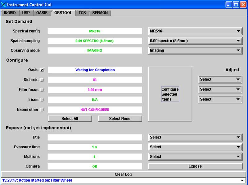
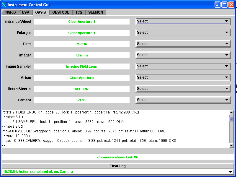
- The instrument mechanisms
can also be configured one by one from
OASIS (Eng) page, it only takes longer and there's a risk of forgetting
something. You should check that you end up with something like this:
- From Taurus set the standard CCD window: window oasis 1 "[1:2059,
1035:3140]" then take an image: glance oasis 1 and display the
file s1.fit with iraf, the spot should be visible.
Checking light reaches INGRID (only
if it will be used on the following night)
- From oasisgui USP page fix the bench, move OASIS Flat OUT of the beam.
Use the IR dichroic. Switch on the Simplex light, with Iris to -150.
- From oasisgui INGRID page, configure Ingrid, for example choose Simplex
H and take the pupil imager OUT.
- From Taurus tke an image: glance ingrid 1 and display s1.fit
with Iraf (use the package ingridql instead of the basic ing
package and display the file using the command idisp. The spot should
be visible.
You can also refer to the Naomi Setup and Observing
Recipes page, which is more oriented towards AO support astronomers, and
is maintained by Chris Benn.
Link to Naomi Engineering
page
Link to Naomi
Astronomy page
 Last updated: 2007 Mar 26 - Olivier Martin