
|
|
 |
The original autoguider failed on 24th Dec 2001 and was replaced on the 19th Jan 2002 with one of the original Loral science chips.
The autoguider should produce a bias level of about 2200 ADU with a noise of 10-15 ADU. There are bright defect columns at columns 259,368,1059,1832 and 1951. Some of these may only be visible if the chip has previously been excited with overexposure. The first 16 columns of the image are underscan, and contain bias level pixels. In addition there is a perfectly circular region of very low sensitivity at the bottom left hand side of the chip ( visible in the default field window). This region has a diameter of approximately 35 pixels. Its appearance in flat fields is a good check of autoguider functionality. The defect column #368 is visible in the image below. It should appear in the default autoguider field window after system startup. It is seen in dark frames taken just after the chip has been flooded with dome lights. Its appearance is another check of autoguider functionality.
![]() Example 5s Field, through
a U filter with the dome lights on.
Example 5s Field, through
a U filter with the dome lights on. 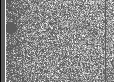 signal
level about 10,000 ADU above bias.
signal
level about 10,000 ADU above bias.
Note that if the autoguider has been inactive for some time , with the dome lights on, the first image will always appear corrupted.
Autoguider images can be saved by using the 'File' pull down menu option on the INT Autoguider window. There is an option to save fits format images, this option should be enabled. Subsequent images are then written to the '/tmp' directory on lpss7 with the filename 'imgfile.fits'. Each subsequent image overwrites the previous until this option is disabled. The image will need to be ftp'ed to lpss8 for display on ximtool.
It is possible that after long observing runs the QE of the Autoguider can fall off, particularly in the blue part of the spectrum. The QE can be checked by referencing the signal produced by the Autoguider with that produced by the EEV science chips (which have a stable QE).
This method involves taking dome flats through U,B and V filters. The signal level at the top right hand corner of chip #1 is measured and compared with the AG signal. This part of chip #1 is closest to the AG and receives the same illumination in a flat field. For the U flat field, the dome lights should be turned on. For the B and V exposures the dome lights should be switched off but the double doors at each side of the dome should be opened and the lights in the corridors switched on. A 5s exposure is then taken with the science array and the signal level measured. A 5 second demanded exposure is then taken with the AG also (remember to open the shutter first), with the acquisition window centre set to coordinates 400,888. This window can be set up using one of the pull down menu options in the autoguider control panel. This window is chosen because it is closest physically to chip #1. This measurement is repeated for each filter. If the QE of the AG is normal , in the U,B and V bands, the signal in ADU (after the bias has been subtracted) in the AG image should be between 4 and 5 times higher than that of the science chip image.
![]() The typical Quantum Efficiency
of this kind of CCD
The typical Quantum Efficiency
of this kind of CCD  (click to enlarge)
![]() QE decay during long observing
runs
QE decay during long observing
runs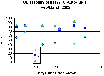 (click
to enlarge)
(click
to enlarge)
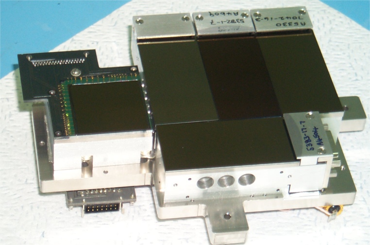
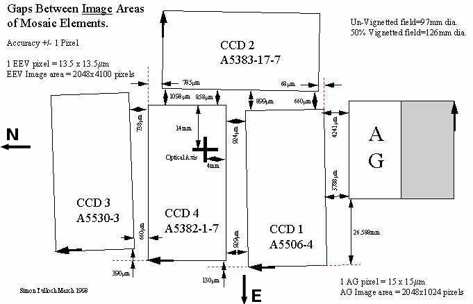
The autoguider is a 2EB Lesser thinned Loral CCD. It is a frame transfer device with an image area of 2048 x 1024 pixels and a storage area of equal size. the pixels measure 15um. These chips have a very good QE but require the surface to be activated with a dry air flood prior to cooling. The surface treatment uses the Passivated Platinum method. The chip reads out from o/pB (bottom left corner of chip as shown in above photo), o/pA being non-functional. The amplifier gain is 1.08e/adu. Note that these wafers were attached to the package with the best functioning serial register at the bottom where the bond wires are attached. Since the wafers are NOT symmetrical this means that some chips need the clocks to vertical phases 1 and 2 transposed to clock the charge in the correct direction. This in fact had to be done when switching to the replacement chip. Non-functioning amplifiers need to be properly isolated by making sure that their associated Summing Well is held low.
![]() The layout of the CCD (pdf)
The layout of the CCD (pdf) 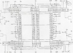
![]() The design of the package
is shown here (pdf), (tif)
The design of the package
is shown here (pdf), (tif)
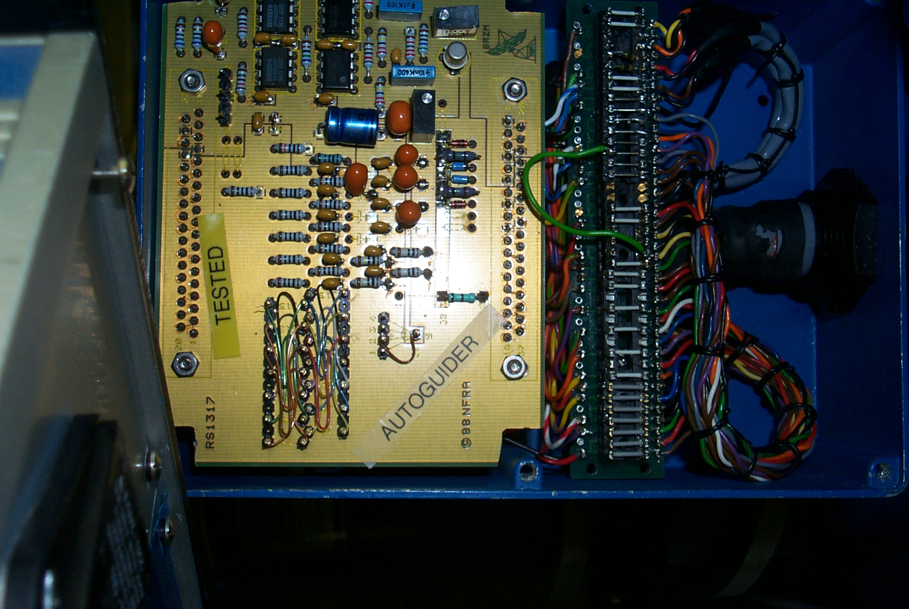
![]() Setup of Pre-amp box for
o/pB Photo , Pdf drawing.
Setup of Pre-amp box for
o/pB Photo , Pdf drawing.
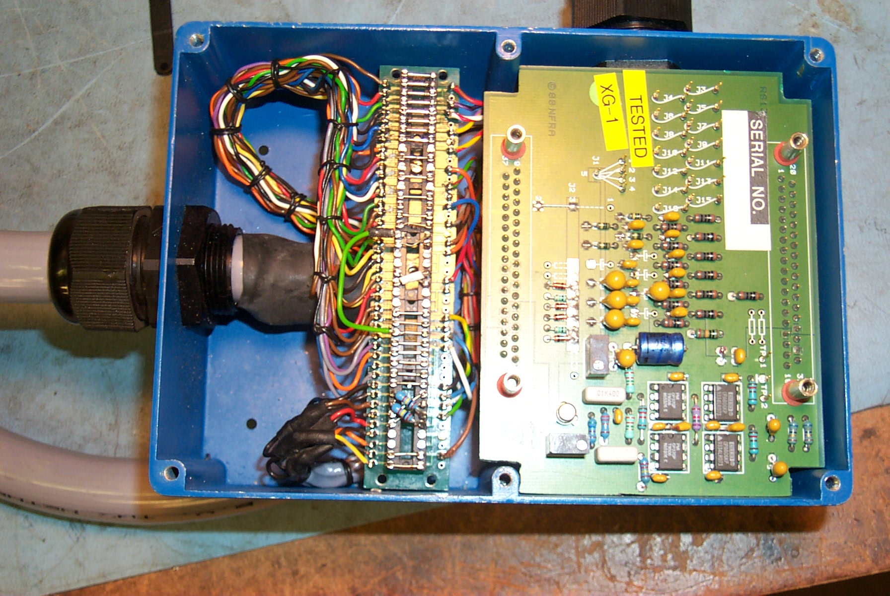
![]() Setup of Pre-amp box for
o/pA Photo , Pdf drawing.
Setup of Pre-amp box for
o/pA Photo , Pdf drawing.
![]() Editing
the waveform tables in the Dutch Autoguider Controller
Editing
the waveform tables in the Dutch Autoguider Controller
There is a spare pre-amp box and Dutch controller for this autoguider. If a controller or pre-amp failure is suspected, the cryostat connector voltages can be checked against the document here (pdf)
The Autoguider is quite linear up to 20,000 ADU . Beyond this it begins to bloom. There is an unusual feature with the demand exposure time; 2.31s must be added to the demanded exposure time to give the actual exposure time.
It is very important that any replacement chip be made coplanar with the science array. The Marconi science array chips are 20.000 mm thick with an error of about +/-15microns. The current autoguider CCD package is much thinner and is mounted on a 16mm thick block to bring it up to the correct level. Additionally, this block had to be shimmed, in a two stage process, to achieve coplanarity. This was done with the aid of the RGO/ATC flatness scanner. Marconi produces a number of standard CCDs in the same style package as the existing science chips. Using this same package would mean that the coplanarity of the autoguider would be achieved automatically. None of these chips, however, combines Frame Transfer architecture with a suitably large sensing area. The closest candidate is the CCD42-40 chip which measures 27.6 x 27.6 mm but it only comes in the full-frame variant.
![]() Marconi
CCD42-40 NIMO Backthinned Broadband AR coating in 3 edge buttable package.
Marconi
CCD42-40 NIMO Backthinned Broadband AR coating in 3 edge buttable package.
The following Marconi chips have been identified as additional candidate replacement autoguider devices. They are all frame transfer but have non-optimal packages :
![]() CCD47-20CCD05-20
CCD05-30 (click for pdf data sheets)
CCD47-20CCD05-20
CCD05-30 (click for pdf data sheets)
The Need for a Frame Transfer CCD
It is difficult to see why a frame transfer device is actually needed in this application. Frame transfer devices allow simultaneous readout and image integration. This really only gives an advantage when the required exposure time is the same or slightly greater than the read out time (or in the INT WFC case , the cycle time of the AG system as a whole , which is approx 8s). If exposure times of less than the AG system cycle time are required, then the chip must be cleared fully before the exposure anyway , thus destroying any image that may have built up in the Image Area of the chip during readout of the previous image. For exposures up to 8s, therefore, there is no advantage to using an FT chip. For an 8s exposure and longer there will be a maximum 50% loss of autoguider efficiency, in an optimally configured system. It is estimated that only 5% of targets require exposure times of 8s or longer. If a non-FT chip is used , then it will still be necessary to mask the lower half of the chip, to eliminate image smear during readout .
Conclusion
The CCD42-40 would seem to be the best autoguider replacement option, despite its full frame architecture. For exposures longer than the cycle time there will be a maximum 50% loss of performance compared to a FT device. This will be more than offset by the ease with which the chip can be made coplanar with the science array. The chip would need to be cleared fully at the start of each autoguider cycle, with the lower half masked off. The area available to acquire guide stars would be 25% less than the current Loral AG, this will be offset by the improved reliability and Quantum Efficiency stability. The chip should be operated with an SDSU controller for highest performance and commonality of software with the planned WHT AG upgrades. The chip itself is capable of the following readout speeds (these assume a full clear is done before each integration) :
![]() 400 x 288 acquisition window
: exposure time + 1320ms
400 x 288 acquisition window
: exposure time + 1320ms
![]() 60 x 60 guide window : exposure
time + 530ms
60 x 60 guide window : exposure
time + 530ms
An SDSU controller will be required to achieve this performance in practice. A small overhead must be added for DAS processing, it is difficult to predict how long this will be, however, as a comparison, uDAS can read out a 400 x 288 window on EEV12 (a chip twice as large as the proposed WFC AG replacement) in only 3.2s.
Readout noise should be in the region of 5e, approximately 3 times lower than the existing autoguider. The QE would be the same as for the science chips.
The CCD42-40 and SDSU controller together would cost £30-35K.