
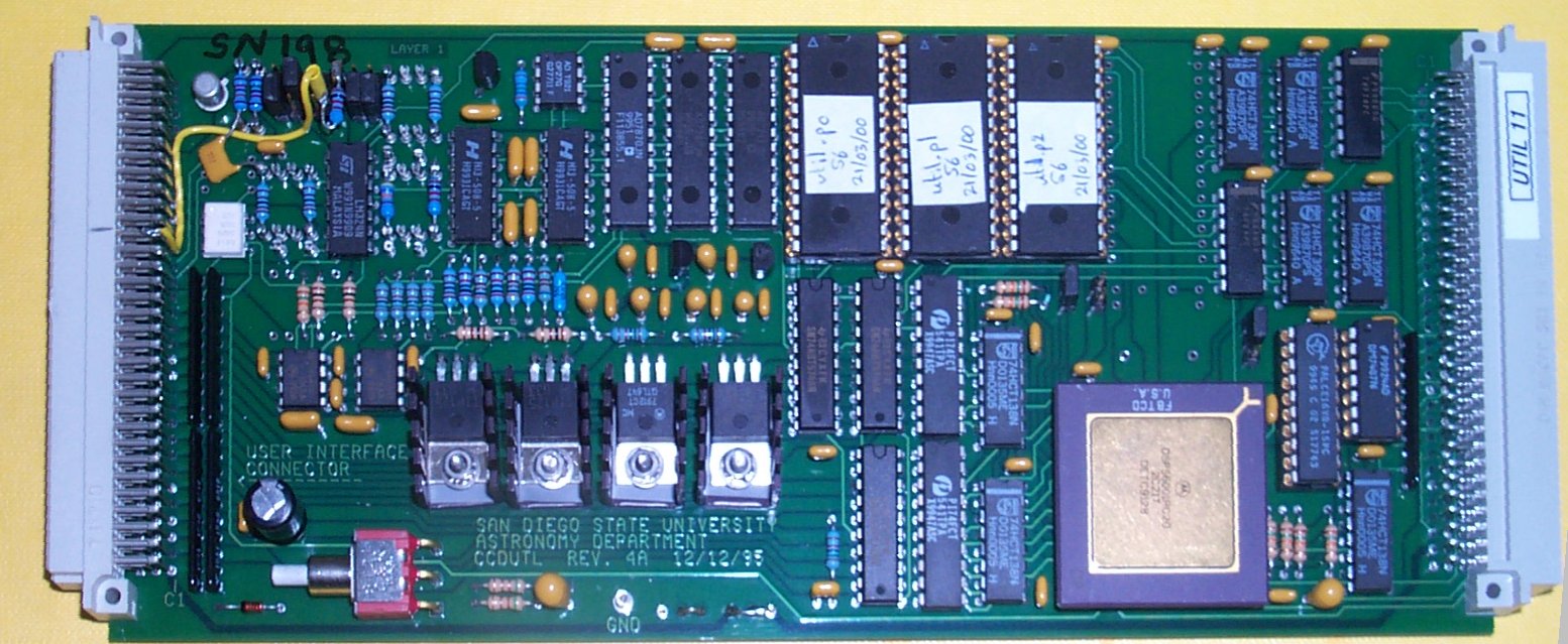
Utility Board Modifications
Photo of the utility
board
In addition, the video board has a small vero-board connected
to its outer edge that controls the preflash LEDs inside each camera cryostat.
The following modifications are required to the Utility
Board :
-
R24 =1K
-
R6 =47K
-
JP8 has three pins, all three must be soldered together
-
JP3 centre pin connected by a yellow wire to external edge
connector pin C21
-
JP4 two pins closest to board edge (1 and 3) soldered together,
centre pin (3) connected to pin furthest from board edge (2) by a 1K resistor.
-
C5 = 100nF ceramic
Circuit
details of the LED driver board and Utility board modifications
Photo of the LED driver board.