Optical Chassis Work Package
Description wht-naomi-93
Document Number
AOW/SUB/RAH/4.4/04/96
Italics usually
indicate additions or changes since the previous version but deletions have not
been indicated. The changes in this version are generally minor. They include
the correction of an inconsistency with another work package, minor editorial
changes and updated document references.
1.0 Optical Chassis
Functional Requirements
1.1 Introduction and
General Requirements
This document should
be read in conjunction with the WP Cover Document AOW/GEN/AJL/6.4/03/96 which
references several other relevant documents. Together these documents
constitute the current requirements for the WHT NGS system. (These documents
are from time to time updated by their authors; readers can ensure they have
the latest versions by checking with the Project Manager.)
1.1.1 Definition
The optical chassis is defined as the entire adaptive-optics optical train with the exception of the wavefront sensor (WFS), the tip/tilt sensor and the WHT. It includes the optical components, their mounts, adjustment mechanisms, calibration sources and the support structures (i.e. baseplates or equivalent) for the optics, the WFS and tip/tilt sensor. The optical chassis will be mounted on a new support structure which will replace the existing GHRIL table. The specifications for the new support structure need to be developed as part of this work package in conjunction with La Palma and other work package suppliers using the structure. Procurement of the structure will be negotiated with the La Palma site. Environmental conditioning of the optical chassis is required as specified in Section 1.3.
1.1.2 Primary Functions
The optical train may be divided into several optical paths. The functions of these paths are summarised below. More detailed information is provided later in the document.
a. The common-path optics must perform at least the following functions:
Interface with the WHT Nasmyth focus and the calibration/alignment source.
Provide optics for imaging the WHT pupil or dominant turbulent layer at the deformable mirror and the WFS entrance pupil..
Include and accommodate the adaptive optics components, i.e. the deformable mirror (DM) and the fast steering mirror.
Provide access for a figure sensor to monitor the DM surface.
Provide an AO-corrected focal plane where light may be directed to the science instrument, the WFS, the tip/tilt sensor and an optical science port as required.
b. The science-path optics will select the wavelength region used by the science instrument and provide a corrected image at the appropriate plate scale over the instrument’s field of view (FOV). (Wavelength selection should be performed with a dichroic beamsplitter.) The science-path optics must also satisfy the instrument’s pupil imaging requirements, e.g. for WHIRCAM the optics must image the WHT pupil at the Lyot stop, and correct for atmospheric dispersion as required.
c. The WFS and tip/tilt sensor paths will allow guide stars to be selected within the available FOV and direct the light from the guide star(s) to the WFS and tip/tilt sensor. The same or different guide stars may be used for tip/tilt sensing and higher-order wavefront sensing. The guide stars may be within or outside the science FOV. Provision must be made for future operation of the wavefront sensor with a laser guide star in the sodium layer. The optics must also maintain the registration of the deformable mirror with WFS lenslet array independent of the guide-star position. The WFS and tip/tilt sensor paths must function to specification in the presence of dithering as required by Science Clause D. Note that atmospheric dispersion correction for the WFS and tip/tilt sensor will probably be provided by optics within those assemblies.
d. The optical science path will provide a partially corrected FOV for use by visible science instrumentation. The initial application will be the use of an acquisition camera. The optics will utilise that section of the FOV not obscured by the pick-offs to the WFS and tip/tilt sensor. Note that the AO system is not primarily intended to provide high image quality in the visible spectral region and the utility of this port may be limited.
e. The calibration and alignment optics will provide a source conjugate to the Nasmyth focal plane for calibration and alignment purposes. The calibration optics will include a WHT-pupil simulator. Provision must be made for distortion mapping of the AO optical train; off-axis positioning of the calibration source is required to accomplish this function. A calibration source is also required for calibration of the wavefront sensor; this source will be injected at the system’s AO-corrected f/11 focus.
1.1.3 General Requirements
The optical path to the science instrumentation port shall follow good design practice for infrared operation, e.g. minimum number of surfaces, low emissivity components. Although the use of cooled optical components is not anticipated, this option may be considered. The need for cold stops and optical components should be investigated as part of the design study. The design should be configured to allow adequate space for existing and future science instrumentation. The space requirements for optical mounts, mechanisms to move components, cameras and cables should be taken into account.
Consideration shall be given to the use of materials and techniques to reduce the effects of temperature changes within the GHRIL. The minimum supporting analysis shall include a first-order study to assess the system's temperature sensitivity. The analysis should demonstrate that the system performance will satisfy all specifications when operating within the temperature limits of the proposed environmental conditioning system.
The optical chassis shall be designed for removal or
installation and alignment within one working day, preferably no more than half
a day.
1.1.4 Guide Star
Selection
The design shall allow selection of any of the five operating modes defined below. These modes are referred to by number elsewhere in the specifications. Note that the centre of the science field will always lie on the system’s optical axis.
1. The WFS and tip/tilt sensor use the science object or the same star in the science field.
2. The WFS uses the science object or a star in the science field and the tip/tilt sensor uses a star outside the science field.
3. The WFS and tip/tilt sensor use the same star outside the science field.
4. The WFS and tip/tilt sensor use different stars outside the science field.
5. The WFS only with the guide star anywhere within the field.
1.1.5 Spectral
Bandwidths
The common path optics shall transmit radiation from 0.4 µm to = 4.1 µm wavelength. The science path shall transmit radiation from 0.82 µm to = 4.1 µm wavelength. The WFS and tip/tilt sensor paths shall transmit wavelengths from 0.4 µm to = 1 µm. Note that when the guide star is within the science field (Mode 1 or 2) the upper wavelength limit for the WFS or tip/tilt sensor is 0.82 µm. Spectral filters for the WFS and tip/tilt sensor are specified in the respective work packages.
1.1.6 Transmission
Table 1 specifies the minimum transmission required from the Nasmyth focus to the input to the WFS and tip/tilt sensor respectively. The mode numbers are those given in Section 1.1.4 above. Transmission values refer to the average over the specified spectral band. Specific requirements are not given for wavelengths in the 0.4 µm to 0.5 µm region where the transmission shall be on a “best effort” basis without requiring new coating development or extensive study.
Table 1
|
|
WFS |
|
Tip/tilt |
sensor |
|
|
Mode |
Bandwidth (µm) |
Transmission |
Bandwidth(µm) |
Transmission |
|
|
1 |
0.50 to 0.82 |
0.49 |
0.50 to 0.82 |
0.02 |
|
|
2 |
0.50 to 0.82 |
0.50 |
0.50 to 1.0 |
0.91 |
|
|
3 |
0.50 to 1.0 |
0.85 |
0.50 to 1.0 |
0.03 |
|
|
4 |
0.50 to 1.0 |
0.89 |
0.50 to 1.0 |
0.91 |
|
|
5 |
0.50 to 0.82 |
0.50 |
|
|
|
|
5 |
0.50 to 1.0 |
0.89 |
|
|
|
For Mode 5 the first specification (0.50 µm to 0.82 µm) applies when the guide star is within the science field and the second applies outside.
These specifications are independent of the polarisation.
All optical coatings must be such that the transmission specifications are satisfied for a minimum period of one year. The use of approved cleaning procedures, as specified below in Section 1.3.3, is acceptable.
1.1.7 Emissivity
All reflecting surface coatings after the Nasmyth flat shall
be selected for maximum reflectivity above 500 nm wavelength with a goal of an
emissivity of < 3% per surface at wavelengths > 2 µm. The total emissivity in the science path after the
Nasmyth flat shall be < 25%. Note that this requirement has implications for
maintaining a clean GHRIL room and protecting surfaces from dust and oil.
1.1.8 Optical Surface Quality
Within the clear aperture of each optical component, the cosmetic surface quality shall be 5/3 x 0.40; K2 x 0.06 in accordance with DIN 3140. The surface roughness shall be = 1 nm rms.(Note that this specification may be relaxed for components that are particularly difficult to manufacture provided analysis indicates no significant effect on the scattered light. Programme approval is required for any such changes.)
1.1.9 Variable
Conjugation
For the baseline design the WHT pupil will be imaged at the deformable mirror. The pupil has a diameter of 1.17 m at a distance of 12.84 m from the Nasmyth focus.
The limited turbulence profiles currently available for the La Palma site indicate that measures to reduce anisoplanatic effects are required to satisfy Clause B. Assuming that a dominant turbulent layer exists, one measure is to make corrections at a conjugate of this layer. The efficacy of this measure requires further analysis and expansion of the JOSE data base. In particular the analysis must study the utility of regions where no wavefront data are available, i.e. the analysis should consider the advantages and disadvantages of wavefront extrapolation or vignetting in such regions.
The system design should provide for conjugation to a
turbulent layer up to a height of 3 km over the 2.9 arcminute field of view. As
a minimum interim requirement for a staged programme, a 72 arcsecond
AO-corrected field with no vignetting for a dominant turbulent layer at a
height of 3 km above the WHT is acceptable. Note that the supplier should give
consideration to the utility, if any, of a larger clear aperture mirror with a
little or no correction beyond the minimum field required. Depending on the
results of the JOSE programme conjugation to greater heights may be required.
The conjugation approach should not adversely affect the pupil-imaging
requirements for the science instrument or significantly increase the system
emissivity.
1.1.10 Variable
System Order
This section is primarily provided for information purposes. The current WFS specifications require the capability to change the sensing geometry to cope (partially) with changes in atmospheric turbulence conditions. The WFS may operate with either 4 or 8 subapertures across the WHT pupil.
1.1.11 Dithering
The design shall maintain the closed loop performance to specification while dithering in accordance with Science Clause D. Specific requirements to accomplish this function are given in Section 1.6 . There shall be no shift of the pupil image relayed to the science instrument during dithering.
1.1.12 Wavefront
Errors
The need to keep the number of optical surfaces in the science-instrumentation path to a minimum will probably place constraints on the optical performance. The wavefront specifications take into account both these design difficulties and the anticipated science needs within the projected operating period of the WHT low-order AO system.
The uncorrected wavefront error introduced by the optics over the path from the Nasmyth focus to the science instrumentation port shall be = 150 nm rms over the central 1-arcminute diameter field. The AO system will usually operate with 8 square subapertures across the WHT pupil. Within any subaperture the on-axis common/science-path wavefront error shall be = 30 nm rms; this high spatial frequency error will not be corrected by the AO system. The off-axis uncorrectable error over this field shall be < 50 nm rms for any subaperture within the pupil. These specifications include design, fabrication and alignment errors except for those introduced by the WHT optics, the deformable mirror and fast steering mirror. The wavefront errors introduced by the deformable mirror and fast steering mirror are covered by separate specifications. Note in particular that the atmospheric-turbulence fitting error is not covered by these specifications. This error is addressed in Sections 1.4.1.5 and 2.0.
Within a 2-arcminute diameter field the design goal for the pupil wavefront error shall be = 170 nm rms with a maximum of 200 nm rms. At the edge of the field (2.9-arcminute diameter) the goal shall be = 265 nm rms with a maximum of 300 nm rms. The same exceptions given in the preceding paragraph apply.
Performance predictions over the field shall be supplied with the proposed design. The results should be presented as rms and peak-to-valley wavefront errors and in the form of spot diagrams shown relative to the Airy disc size at 2.2 µm wavelength.
Non-common path wavefront errors between the science path and the WFS or tip/tilt sensor should not exceed 100 nm rms. The ray trace results should show a spot diagram for each WFS subaperture that falls within the Airy disc diameter at 0.6-µm wavelength. Note that reduction of chromatic aberrations below 0.5-µm wavelength is not critical and, as a design goal, the aberrations should not produce a spot more than 10% larger than the diffraction-limited diameter. The optical design results should indicate the variation in non-common path wavefront error over the field; these results are needed to assess the difficulty of calibrating out the errors.
Refocusing of the WFS, e.g. to remove field curvature, is acceptable for guide stars located outside of the science field.
1.1.13 Beamsplitters
Any proposed use of conventional beamsplitters must be supported by evidence that adequate measures will be taken to significantly attenuate second surface reflections. Furthermore, analysis should be performed to verify that conventional parallel-plate beamsplitters in non-collimated beam paths will not introduce unacceptable aberrations. Pellicles are acceptable as beamsplitters provided measures are taken to guard against dust, damage and microphonic effects. Note that the aberrations of any beamsplitters (except pellicles) in non-collimated beams must be included in the optical design.
1.1.14 Scattered Light
Measures shall be taken to reduce scattered light to a minimum in the science instrumentation, the calibration optics and WFS/tip/tilt sensor paths. Baffles should be used where appropriate and optical mounts should be black anodised or painted with non-flaking flat black paint. All optical surfaces should have a low surface roughness, preferably < 1 nm rms. The optical design should include an estimate of the signal/scattered light ratio at the tip/tilt sensor and WFS when operating with a visual magnitude 16 star near the galactic equator.
1.1.15 Line of Sight and Access to Nasmyth Focus
A direct line of sight along the length of bench for access to the Nasmyth focus by an alignment telescope shall be provided. If the removal of optical components is required to obtain the line of sight, the component must be either kinematically mounted or mounted on slide. Ease of removal and replacement without requiring realignment are essential.
Rapid ( < 1 hour) access to the f/11 focus is desirable for small experiments or alignment activities not requiring use of the AO system. This provision will reduce the need to remove the entire AO system. The system should be returned to its original state in < 2 hours.
1.1.16 Correction of Atmospheric Dispersion
Specific requirements
for an atmospheric dispersion corrector
(ADC) for the science path are given in Section 1.5.2. The wavefront sensor and
tip/tilt sensor suppliers are responsible
for providing ADCs for these assemblies.However a common ADC for these
assemblies may be the optimum solution for the AO system design. Therefore the
optical-chassis supplier should work closely with the wavefront-sensor and
tip/tilt sensor suppliers to arrive at the best system configuration.
1.1.17 Support Structure
As already stated in Section 1.1.1, the optical chassis will be mounted on a new support structure which will replace the existing GHRIL table. The specifications for the new support structure need to be developed as part of this work package in conjunction with La Palma and other work package suppliers using the structure. Procurement of the structure will be negotiated with the La Palma site. Note that the support structure is expected to house not only electronics for the optical chassis but other electronics for the Real Time Control System.
1.1.18 Handling Trolley
A handling trolley is required for the support structure.
This trolley will provide a convenient means of transporting the support
structure and optical chassis at La Palma, e.g. for checkout in the WHT
instrument preparation room. Specifications for this trolley shall be developed
by the optical chassis supplier. Consultation with La Palma staff is required
during the specification and design process. The specifications are subject to
approval by the programme.
1.1.18 Beam Height
The Nasmyth-focus optical axis lies about 150 mm above the surface of the existing GHRIL optical table. The optical-chassis supplier is free to select a different height subject to approval by the programme. Note that all parties likely to be affected by a height change must be kept informed of any proposed change and invited to comment. Arrangements for transferring and discussing such information will be agreed with the programme management.
1.1.19 Health and Safety
Potential safety hazards shall be identified and measures
taken to protect personnel, e.g. warning notices, covers with interlocks.
Handling procedures and lifting aids, e.g. eye bolts, shall be provided for
heavy items.
1.2 Space Allocation
The programme anticipates that the existing GHRIL optical table will be replaced with an assembly designed to support the optical chassis and accommodate most electronics. The size of the existing table should be used as the starting point for the optical design. Figure 1 indicates the size and location of this table. Some optical components may need to be mounted beyond the front edge of the existing table where the space is limited, particularly in the region of the WHT image derotator. Figure 2 shows the space envelope for the front of the bench. Sufficient space must be provided for the tip/tilt sensor, the wavefront sensor, WHIRCAM and future instrumentation as required by Clause E. The optical-chassis supplier will be expected to work closely with the programme, the suppliers of the tip/tilt sensor, the wavefront sensor, the Real-Time Control System and the appropriate WHT staff.
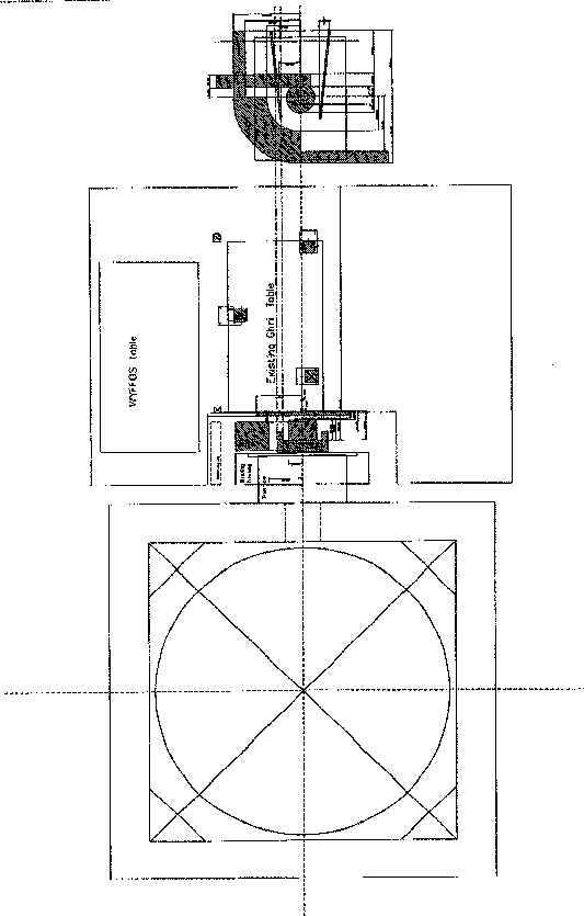
Figure 1. General layout of the GHRIL showing the existing GHRIL table
and components at the front of the bench..
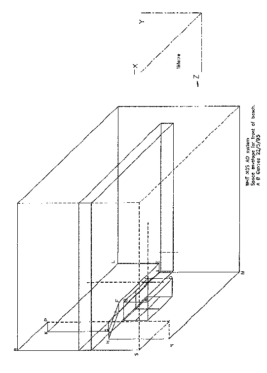
Figure 2. Space envelope for the front of the existing GHRIL table.
(View rotated clockwise by 90 degrees).
1.3 Environmental
Requirements
1.3.1 Overall Requirements
That part of the AO system installed in the GHRIL must operate within specification over a temperature range of -10oC to 20oC. An environmentally conditioned enclosure may be required for the optical chassis to maintain a more limited temperature range (TBD) and a clean environment although a completely open system is most likely initially. If needed, the provision of such an enclosure will be the responsibility of the optical-chassis supplier. Global control of the GHRIL environment is the responsibility of La Palma.The optical-chassis supplier will be expected to work closely with La Palma and the AO programme in this area.
Equipment installed in the WHT control room must operate to specification over a temperature range of 10oC to 30oC. All specifications must be met at pressures ranging from 550 to 1050 mbar. Although the equipment in the GHRIL will usually.operate in low humidity, it must withstand exposure to humidity levels approaching 100%. Protective measures, e.g. heaters, covers, may be employed if needed; note that the system will not be operated when such protective measures are employed. Local turbulence effects introduced by any heat source on or near the optical table must not affect the AO system performance.
The environmentally conditioned enclosure, if any, should provide a clean operating environment for all components mounted on the optical chassis. The environment shall be such that the relative transmission over the paths from the Nasmyth focus to the science port, the WFS and the tip/tilt sensor respectively shall not decrease by more than 5 % over a 1-month period. Any measures used to maintain this environment shall not adversely affect the system performance.
1.3.2 Vibration and Stability
All AO components and their mounts shall exhibit good stability consistent with the optical and environmental requirements and have high resonant frequencies (> 1 kHz). Uncorrectable tip/tilt jitter induced by vibration sources both internal and external to the GHRIL shall not exceed 30 nrad rms (0.006 arcsecond rms) in object space. (Vibration data for the GHRIL are obtainable from the RGO.) Uncorrectable tip/tilt jitter includes jitter beyond the response of the tip/tilt sensor/FSM and WFS/ deformable mirror subsystems and jitter at any frequency within the non-common-path regions between the science port and the AO components. Microphonic effects are also included in this specification.
1.3.3 Cleaning
Procedures
Cleaning procedures must be developed for all optical components and successfully demonstrated on witness samples of all coatings prior to use on the AO optical system.
All such procedures must be adequately documented for use by optical technicians or engineers.
1.4 Common-Path Optics
The primary functions of the common path optics were specified in Section 1.1.2 above. These optics must cover a 2.9 arcminute field of view which is set by the new WHT image derotator. The common path optics are essentially a unit magnification relay stage with a collimated region to accommodate the deformable mirror and fast steering mirror. Note that the latter may be a collimating optic. Any proposal to use a relay stage that does not operate at unit magnification requires programme approval. The common path optics must provide a variable conjugation capability as specified in Section 1.1.9 above. Sections 1.4.1 to 1.4.3 specifically address the deformable mirror and fast steering mirror. Although these two components have nominally been included in this work package, potential suppliers are warned that the components may be handled as separate procurements or existing components may be used. Such actions may be taken if they offer significant advantages to the programme.
Note that several other specifications given above apply to the common-path optics and other sections of the optical train.
1.4.1. Deformable Mirror and Drivers
1.4.1.1 General Requirements
The mirror and its drivers shall be based on designs that have provided good performance with high reliability. A mirror with a continuous facesheet is desired but other designs, e.g., segmented, may be acceptable provided the system requirements are satisfied. In particular the emissivity characteristics of other mirror types must be addressed. Use of an existing mirror as an interim measure may be acceptable. The mirror need not satisfy every specification but it must be shown to provide overall benefit to the programme, e.g. significant cost and schedule advantages. The number of actuators, degrees of freedom and the actuator layout must be compatible with the wavefront sensor subaperture configuration and the phase reconstruction algorithm(s). The wavefront sensor will have a square array of subapertures with 8 subapertures across the 4.2 m diameter telescope aperture. The baseline phase reconstruction algorithm will provide phase values at each corner of the subaperture. With this configuration 9 actuators would be required across the WHT pupil diameter; note that, for reasons given below, actuators will be needed beyond the pupil diameter.
Electro-strictive actuators or piezo-electric are preferred. If magneto-strictive actuators are proposed, evidence must be presented to show that hysteresis, heat dissipation and magnetic cross coupling are not problems for this application.
1.4.1.2 Clear Aperture and Active Area
The DM clear aperture shall be sufficient to satisfy requirements for the variable conjugation capability specified in Section 1.1.9. Assuming a conventional deformable-mirror design, the actuator spacing along the x and y axes should be 7± 0.1 mm within the pupil image. Note that existing mirrors with actuator spacings up to 8 mm may be used provided an effective upgrade path to satisfy all requirements is proposed. The distribution of actuators in the annulus surrounding the WHT pupil image requires analysis based on the results of the JOSE programme. The adaptive optics programme will support this analysis as required.
1.4.1.3 Actuator Stroke and Hysteresis
Each actuator shall provide a local surface stroke of at least 4.1 µm ; a smaller stroke between adjacent actuators is acceptable but this should be at least 1 µm. Actuator hysteresis should not exceed 5 percent over the range with a design goal of = 2 percent. The use of circuits or a figure sensor to correct hysteresis is acceptable. Any approach proposed to reduce hysteresis must be described. Data on the temperature sensitivity of actuators shall be provided. The mirror should be equipped with a thermocouple to monitor the mirror temperature.
1.4.1.4 Actuator Reliability and Repair
An operational lifetime of at least 3000 hours is required with a goal of 10,000 hours. The failure
of one actuator is acceptable during this period. As a design goal, the failed
actuator, if any, shall be detachable from the facesheet. A mirror design with
readily replaceable actuators will be considered provided the design does not
represent a major departure from an existing high-reliability design.
1.4.1.5 Fitting-Error Coefficient
The atmospheric-turbulence fitting-error coefficient, µ, shall not exceed 0.4 with a design goal of = 0.3; the effect of fitting error is included in the system error budgets given in Section 2.0. The following equation defines the coefficient for the purposes of this specification.
s2 = µ ( d / ro )5/3
where s2 = variance of the residual wavefront error
d = actuator spacing (52.5 cm projected at WHT pupil)
ro = atmospheric turbulence coherence length (= 8 cm)
With reference to the error budgets for clauses A and B we have:
µ = 0.4 (maximum value)
d = 0.525 m
ro = 1.05 m (20-cm visible ro scaled to 2.2 µm).
Substituting these values in the above equation gives s2 = 0.125 rad2, which is consistent with the error budget.
1.4.1.6 Facesheet and Actuator Resonances
The first resonant frequency of the facesheet and the actuators shall be > 2 kHz with a design goal of = 10 kHz.
1.4.1.7 Uncorrected and Corrected Surface Flatness
With no correction, i.e. zero voltage, the mirror surface
shall be flat to 70 nm rms. With the mirror surface under active control a
surface flatness of 45 nm rms shall be achieved. This specification applies
only within the clear aperture.
1.4.1.8 Optical Coating
The mirror surface shall be provided with a durable coating providing = 95 percent reflectance (goal) in the 0.4 µm to 0.5 µm spectral region and = 97 percent reflectance from 0.5 µm to 0.8 µm. Beyond this region the reflectance shall = 98 percent to = 4 µm.
1.4.1.9 Drivers
Mirror drivers (sometimes known as power amplifiers) that utilise the reconstructed phases to drive the deformable mirror to the required figure shall be provided. The combination of the deformable mirror and its drivers shall satisfy all specifications given above that relate to active control of the mirror.
If there is a risk of damage to the mirror as a result of large interactuator displacements or overvoltage then protection circuitry shall be included in the drivers' design, e.g. the relative displacement between adjacent actuators might be limited to 1 µm.
The driver design should include any circuits needed for hysteresis reduction, the correction of actuator non-linearity and the equalisation of actuator strokes. The driver circuits shall be supplied mounted as a single assembly.
The capability to monitor the drive signals to the deformable mirror actuators shall be provided. Provision shall be made to transmit these signals and any other essential status signals to the WHT control room; the use of a fibre-optic data link is preferred. A controller for controlling key functions, e.g. power on/off, from the WHT control room shall be provided.
1.4.1.10 Deformable
Mirror and Drivers' Response
The mirror shall achieve 95 percent of full stroke in = 400 µs with a goal of < 200 µs. Full stroke, within the fitting error limits, shall be attained in = 1 ms.
1.4.1.11 DM Incident Angle
The incident angle at the deformable mirror should be = 10 degrees. The small incidence angle is required to keep the one-dimensional misregistration between the actuators and the WFS to within the error-budget allotment.
1.4.2 DM Figure Sensor
Sufficient space shall be provided to view the DM clear aperture with a figure sensor (option TBD). Normal incidence viewing of the mirror surface is preferred but viewing at another angle may be acceptable if justification is given.
1.4.3 Fast Steering
Mirror
1.4.3.1 General Requirements
(Note that the following discussions of the tip/tilt sensor requirements are provided primarily for information purposes.)
A tip/tilt sensor and the fast steering mirror (FSM) will usually operate as a closed-loop subsystem. In this mode the tip/tilt sensor-FSM subsystem provides a tilt-stabilised image to the system’s wavefront sensor. The capability to occasionally operate as an independent closed loop system is also required, i.e. to provide only tip/tilt correction. Detailed specifications for the tip/tilt sensor are given in the Tip/Tilt Sensor Work Package Description (Document Number AOW/SUB/RAH/1.6/04/96).
The tip/tilt sensor-FSM subsystem must correct for the three sources of tip/tilt error given below.
1. Atmospheric turbulence
2. Pointing jitter of the WHT
3. WHT long-term pointing drift
The tip/tilt sensor will measure the combined effect of all three error sources. The FSM will primarily correct for the first two error sources; any small-amplitude, high-frequency residual error will be passed on to the wavefront sensor and deformable mirror. The FSM significantly reduces the stroke requirements that would otherwise be placed on the deformable mirror. To avoid an excessive range requirement for the FSM during long observing periods, the long-term pointing drift will be corrected by feeding low-bandwidth or DC tip/tilt sensor error signals to the WHT control system.
The FSM and its associated drive circuits should be based on existing technology that has been demonstrated to provide high reliability. The FSM may perform two optical functions, e.g. it may provide tip/tilt correction and also serve as a collimating optic. Analysis is required to demonstrate that a dual-function mirror has no adverse effect on system performance.
Note that certain specifications are subject to revision
when sufficient JOSE data are available and the data have been analysed. Some
requirements are currently based on extremely limited observations made at the
WHT under stressing conditions.
1.4.3.2 Clear Aperture
The FSM optical clear aperture is driven by the requirement to image the dominant turbulent layer, if present, at the DM. Consideration may be given to the use of existing mirror designs, particularly for a staged programme, that do not fully satisfy the requirements of Section 1.1.9. The proposed use of a slightly undersize mirror must provide significant cost and schedule benefits to the programme. As a minimum requirement, however, the mirror should cover a 72 arcsecond field with no vignetting for a dominant turbulent layer at a height of 3 km above the WHT. A mirror clear aperture in the range 95 mm to 135 mm diameter is anticipated.
1.4.3.3 Tip/Tilt Range
The mirror surface shall cover an angular range of = 1 mrad over two orthogonal axes.
Provision shall be made to protect the FSM from being driven to the limits of its operational range, e.g. as the result of excessive WHT pointing drift. When the FSM has reached a critical point in its range, a signal shall be sent to the telescope control system to remove the undesired offset. Determination of the critical point will depend on the rate of drift and the response of the telescope control system. The tip/tilt sensor and FSM must maintain a stable loop closure during this mode.
1.4.3.4 Frequency Response
The frequency response of the FSM shall extend to = 1 kHz
(-3 dB point).(This specification is subject to revision when sufficient JOSE
data are available.)
1.4.3.5 Resonances
The lowest resonant frequency of any part of the FSM
assembly shall be = 1.5 kHz. (This specification is subject to revision when
sufficient JOSE data are available and a supporting mechanical analysis has
been performed. The optical-chassis supplier is expected to be involved in this
activity.)
1.4.3.6 Optical Coating
The mirror surface shall be provided with a durable coating providing = 95 percent reflectance (goal) in the 0.4 µm to 0.5 µm spectral region and = 97 percent reflectance from 0.5 µm to 0.8 µm. Beyond this region the reflectance shall = 98 percent to = 4 µm.
1.4.3.7 Surface Quality and Accuracy
Within the specified clear aperture the cosmetic surface quality shall be 5/3 x 0.40; K2 x 0.06 in accordance with DIN 3140 and the surface shall be plane (or parabolic) to within 25 nm rms. Within any 1-cm diameter area inside the clear aperture the surface shall be plane (or parabolic) to 10 nm rms. The surface roughness shall be = 1 nm rms.
1.4.3.8 Mirror Orientation
As a design goal the mirror shall operate to specification in any orientation. The intent is to allow for possible future use in other AO systems, e.g. with a Cassegrain mount.
1.4.3.9 Mounting
The mirror assembly shall have a flat surface with three threaded holes for mounting purposes. Drawings shall be supplied in the design stage to indicate the mounting configuration.
1.4.3.10 Mirror Cover
A mirror cover shall be provided to protect the mirror surface when not in use.
1.5 Science Path
1.5.1 General
Requirements
The near-term requirement is to provide optics to interface with WHIRCAM. This instrument is a modified UKIRT camera housing a 256 x 256 InSb array. The camera operates from 0.8 µm to 5 µm with high quantum efficiency. Anticipated future requirements are given in Science Clause E and these must also be taken into account. The science path optics shall provide a plate scale of 0.05 arcsecond/pixel at WHIRCAM and image the WHT pupil at its Lyot stop
A remotely controlled assembly is required to allow any of three dichroic beamsplitters to be inserted in the science path .The function of each beamsplitter is to reflect the longer wavelengths ( =0.82 µm) to the science instrument and transmit the shorter wavelengths to the WFS and tip/tilt sensor. Three dichroic beamsplitter options are currently being considered:
1. A standard dichroic beamsplitter covering the science field, i.e. WHIRCAM in the near term. This is used when there is no lack of light in the WFS arm (Clause A) and where short wavelengths in the science arm are important. The dichroic coating shall be based on existing coating technology and it shall be designed for maximum reflectance at wavelengths = 0.82 µm. The beamsplitter region outside of the dichroic area shall be antireflection coated for good performance over the 0.5 µm to 1 µm spectral region.
2. A dichroic beamsplitter giving high transmittance at wavelengths below 1 µm and high reflectance at wavelengths > 1 µm. This is used for faint on-axis guide stars where the maximum possible radiation must be made available to the WFS . The geometry covers the science field as above.
3. A long-slit spectroscopy dichroic beamsplitter. This uses the standard coating but the geometry is changed to a rectangular patch only covering the spectrograph slit opening.
1.5.2 Atmospheric Dispersion Corrector (ADC)
An ADC is required for all wavelengths below K band to 0.82 µm. The residual chromatic dispersion over this spectral region for zenith angles to 60 degrees shall be <0.025 arcseconds in WHT object space. The ADC shall not introduce a pupil shift greater than TBD of the Lyot stop diameter. The ADC shall be readily removable when not needed, e.g. for narrow band observations.
1.6 WFS and Tip/tilt sensor Optical Paths
The pick-offs for the WFS and tip/tilt sensor should be located at or near the corrected focal plane of the common-path optics. The pick-off approach should be such that its aberrations are independent of the field position. The tip/tilt sensor pick-off should be located before the WFS pick-off to allow the latter to be refocused when operating with laser guide stars. The pick-offs will direct f/11 beams from the selected guide stars to the WFS and tip/tilt sensor respectively. Note that the f/11 beam assumes that the common-path relay optics operate at unit magnification. Any proposed departure from unit magnification must be justified as it affects the interfaces with other components.
The pick-off optics (but not their supporting stages) will be the responsibility of the WFS and tip/tilt sensor suppliers. The optical-chassis supplier will however be expected to participate in the design of these optics and their interfaces with the optical chassis. The optical requirements for the pick-offs given in this section are therefore provided mainly for information purposes although the optical-chassis supplier must be satisfied that any proposed pick-off design satisfies the system requirements.
Mapping of the DM image at the WFS lenslet array must be maintained over the full field.
Any obscuration of the optical science port by the pick-offs shall be kept to a minimum.
An obscuration of < 4 x 4 arcseconds is a design goal. There shall also be provision to insert a calibration source for the WFS (see Wavefront Sensor Technical Specifications,
Document AOW/SUB/RAH/2.9/04/96); this source is the responsibilty of the WFS supplier. The optical-chassis supplier must work with the WFS supplier to determine the interface requirements.
The tip/tilt sensor pick-off shall have three remotely interchangeable options as specified below.
1. Full reflection to the tip/tilt sensor.
2. 4% (approximate) reflection to the tip/tilt sensor (assumes uncoated surface reflection).
3. Transmission of all light to the WFS ( used when the WFS provides tip/tilt
correction).
The pick-off ranges and speeds given below in Table 2 assume unit-magnification common path optics. If the magnification is not unity the table must be scaled accordingly. The x and y axes are parallel to the f/11 corrected focal plane with the x axis horizontal and the y axis vertical. Note that several specifications in this table relate to the requirements for dithering. The stages needed to meet these requirements shall be provided as part of the optical chassis.
Table 2.
|
|
WFS |
|
Tip/tilt sensor |
|
|
|
|
|
|
|
|
Axis |
Requirement |
Axis |
Requirement |
|
|
|
|
|
|
|
|
X |
Range:± 25 mm |
X |
Range:± 25 mm |
|
|
|
Step size: = 5 µm |
|
Step size: = 5 µm |
|
|
|
Repeatability: = 2.5 µm |
|
Repeatability: = 2.5 µm |
|
|
|
Speed: = 1.25 mm/second |
|
Speed: = 1.25 mm/second |
|
|
|
|
|
|
|
|
Y |
Range:± 25 mm |
Y |
Range:± 25 mm |
|
|
|
Step size: = 5 µm |
|
Step size: = 5 µm |
|
|
|
Repeatability: = 2.5 µm |
|
Repeatability: = 2.5 µm |
|
|
|
Speed: = 1.25 mm/second |
|
Speed: = 1.25 mm/second |
|
|
|
|
|
|
|
|
Z |
Range: 25 mm |
Z |
Range:± 1 mm |
|
|
|
Step size: = 50 µm |
|
Step size: = 50 µm |
|
|
|
Repeatability: = 25 µm |
|
Repeatability: = 25 µm |
|
|
|
Speed: = 1 mm/second |
|
Speed: = 1 mm/second |
|
|
|
|
|
|
|
|
Angular |
Tolerance (tip & tilt) : = 0.23 |
mrad |
|
|
1.7 Optical Science
Port
The region of the field not used by the WFS and tip/tilt sensor pick-offs shall be made available for use by optical science instrumentation. Note that the AO system is not designed to provide a high degree of correction at wavelengths below 0.82 µm.
An acquisition camera will be initially be used at this port. The fore-optics for this camera are currently designated part of the optical chassis. Although this component has nominally been included in this work package, potential suppliers are warned that the component may be handled as separate procurements or an existing component may be used. Such actions may be taken if they offer significant advantages to the programme.
Two candidates are currently being considered for the acquisition camera. One is a 2048 x 2048 pixel bare CCD camera with the capability to view faint sources (V > 26) using moderate integration times (20 seconds maximum).The camera would probably be used in two modes. One would allow survey of the full field and the other would allow detailed inspection (0.1 arcsecond/pixel) of a limited area (< 256 x 256) , e.g. for spectroscopic acquisition. The other candidate is an RGO 2048 x 4096 pixel EEV-based camera. Further information will be made available later. The optical-chassis supplier will be expected to work closely with the programme in this area.
1.8 Alignment and Calibration Optics
1.8.1 Calibration Source at Nasmyth Focus
Provision shall be made to remotely insert a point source at the f/11 Nasmyth focus at any location within the field using an x-y translation stage. The spectral bandwidth of this source shall be sufficient to provide radiation to the science instrumentation, the wavefront sensor and the tip/tilt sensor for alignment and calibration purposes. Provision shall be made to replace this source with a sodium lamp emitting at 589 nm for possible future operation with a sodium-layer laser guide star.
A filter holder is required to hold up to four spectral and/or neutral density filters (TBD) to simulate different stellar types. The filters shall be remotely interchangeable. Note that there should be no focus shift when changing from visible to IR operation. There shall also be provision to increase the spot size to simulate the time-averaged size of turbulence-degraded spots for calibration of the WFS and tip/tilt sensor. The shortest visible atmospheric coherence length specified for system operation is 8 cm.
The capability of introducing small ( amplitude and frequency are TBD) angular motions of the beam from this source is required for functional checks of the AO system.
1.8.2 WHT Pupil Simulator
The optical system associated with calibration source specified shall simulate the WHT exit pupil which has a diameter of 1.17 m at a distance of 12.84 m from the Nasmyth focus. Note that the pupil simulator and source must be designed for system checkout in the WHT instrument preparation room.
1.8.3 Pre-correction Camera
A camera shall be provided to view the Nasmyth focus preferably using the same optic that inserts the light from the calibration source. The choice of camera shall be part of the design process; the selection shall be subject to programme approval. A DALSA area-scan camera or an EEV Super Photon camera are suggested.
1.8.4 Distortion Calibration
Provision shall be made to map the optical-system distortion over the full field of view. This information is required for astrometry purposes. The calibration should be carried out using the movable point source specified above and the process should be automated for convenience and speed. The step size for the source x-y stage shall be = 5 µm with a repeatability of = 2.5 µm for both axes over the full field. Other techniques may be proposed but they must be described in sufficient detail for appraisal by the programme. The number of calibration points within the field should be determined as part of the optical design process.
1.8.5 Wavefront-Sensor Calibration Source
This source is the responsibility of the WFS supplier and
the following paragraph is provided primarily for information purposes.The
optical-chassis supplier must provide sufficient space to accommodate this
source (design TBD) and satisfy the interface requirements (TBD).
Provision shall be made to inject a reference plane wavefront from a light source for the WFS phase-gradient calibration. The wavefront shall be produced by inserting the light from the source at a point close to the AO-corrected f/11 focus. Light from this source will pass through the WFS collimating lens to produce a plane wavefront. The tilt of this plane wavefront shall be remotely and independently variable in the x and y axes over the maximum operational phase gradient range of the wavefront sensor. This function may be provided by the WFS pick-off stage. The wavefront tip/tilt shall be calibrated by independent means to an accuracy at least a factor of two (2) better than that required for the wavefront sensor. The spectral bandwidth of the source shall cover 0.4 µm to 1 µm and its brightness shall be equivalent to at least a magnitude-8 star. The output of source shall be filtered as needed using remotely interchangeable neutral density filters of 1.0 ± 0.1 density and 2.0 ± 0.1 density. The filters shall be manually removable from their holders for replacement by other filters of the same size if desired by the user.
Further information on the WFS calibration is provided in the Wavefront Sensor Technical Specifications (AOW/SUB/RAH/2.9/04/96).
1.8.6 Calibration of Non-Common Path wavefront Errors
Provision shall be made for the calibration of non-common path errors between the science path and the WFS path. This will involve the injection of a point source or collimated beam (depending on the design configuration) at the separation of the two paths to allow the WFS to measure the non-common path error. It is expected that the wavefront error will need to be measured at several points across the field to generate a catalogue of look-up tables for use in the wavefront reconstruction. The number of points selected will depend on the magnitude and rate of change of the non-common path aberrations over the field.
2.0 Error Budgets
Figures 3 and 4 show the system error budgets for Science Clauses A and B respectively. For consistency all errors have been expressed as phase variances in radian2 at a wavelength of 2.2 µm. For many work packages the errors have been converted to units that are more appropriate and easier to interpret.
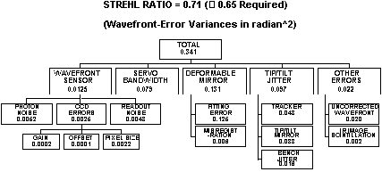
Figure 3. Clause A error budget.
Figure 3 shows the error-budget for the Clause A conditions with 8 subapertures/diameter over the WHT pupil diameter. The dominant effect is the deformable-mirror fitting error. Because the light level is high, i.e. magnitude 8 star, the wavefront sensor errors are small. The budget assumes that the wavefront sensor CCD has been calibrated to specification and the pixel size errors do not exceed 1 µm rms. A conventional centroiding algorithm was used in determining the budget for the CCD errors. The tip/tilt jitter includes an allowance of 30 nrad (0.006 arcsec) rms for jitter on the optical bench induced by telescope motion and moving bench components; this jitter is in addition to the 70-nrad (0.015 arcsec) rms tip/tilt sensor/FSM error. The “misregistration” box refers to errors associated with the incorrect mapping of the mirror actuators at the wavefront-sensor lenslet array, e.g. due to a non-zero incident angle at the deformable mirror. The optical design is such that the deformable mirror is imaged at the lenslet array. The allowance for the uncorrected wavefront error includes only those errors specified for the AO system. The contribution from the WHT optics was not known at the time of writing but this information is being sought.
The error budget in Figure 3 gives a Strehl ratio of 0.71 which is comfortably above the specified value of 0.65 for Clause A. Note, however, that several assumptions were made in deriving the error budget. In particular, the error budget may be revised when adequate turbulence data from the JOSE programme are available. Furthermore, there may be some small sources of error that have been omitted.
The ability to satisfy Clause B requires that the system operate with dim stars, e.g. visual magnitude of at least 15 or 16, and that the atmospheric conditions provide a guide field diameter of about = 3 arcminutes (Note that this is about the field limit of the new WHT image derotator.) Data on the latter condition will be provided by the JOSE programme.
The error budget shown in Figure 4 is for an on-axis magnitude 16 guide star; operation with a dichroic beamsplitter that allows the WFS to be used over its maximum spectral bandwidth was assumed. An integration time close to the assumed atmospheric time constant was used and, as a result of the low sample rate, the CCD noise was assumed to be 3 noise electrons/pixel. This noise level is claimed to be achievable by at least one CCD supplier. Note that in the absence of representative JOSE data, the atmospheric time constant was based on a Bufton wind profile and a modified Hufnagel-Valley turbulence profile. Figure 4 shows that several errors have increased significantly over those shown in Figure 3. An increase in sources of error such as photon noise should be expected at these low light levels. The error budget analysis for Clause B brought out the need for accurate calibration of the WFS CCD background offset.
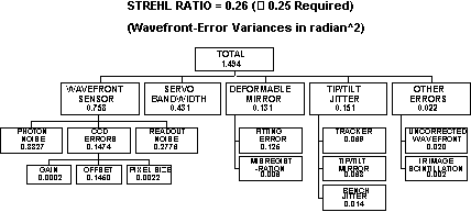
Figure 4. Clause B error budget.
The model used for the error-budget analysis did not have the capability to explore any potential benefit from modal techniques and turbulent layer conjugation. These approaches will be explored using propagation codes.
3.0 Deliverable items
In addition to the optical chassis and all associated hardware, other deliverables include software and licenses, review documents, test procedures and reports, reports on analyses and simulations, user manuals, and test equipment paid for by the programme.
The delivery location is expected to be the location for system integration (TBD).