TECHNICAL DESCRIPTION OF
NAOMI wht-naomi-67
Internal document number AOW/GEN/AJL/7.0/07/96/Technical Description of
NAOMI
Version date 18 July 1996
CONTENTS
1.
Introduction
2. System Overview
3. System-Level Features
4. Key Adaptive Subsystems
5. Optical performance specifications
6. Opto-mechanical system design requirements
and goals
7. Alignment and Calibration
8. Global Opto-Mechanical Components
9. Software Architecture
10. Real-Time Control system
11. Observing System control interfaces.
12. User interfaces
13. Observational capabilities and procedures
14. Telescope, GHRIL and supported
instruments
15. Software and computing standards;
maintenance issues
16. Handling and operational support
requirements
17. Lifetime and downtime
18. Maintenance
19. Safety
20. Documentation
21. Future Development
22. References
23. Modelling Assumptions
24. Deliverables List (TB completed)
25. Summary of NAOMI upgrade paths
1. Introduction
This document provides a technical summary of the NAOMI system designed to meet the requirements described in the document Top Level Scientific and Operational Requirements for NAOMI. As each major technical feature or specification is introduced the table format illustrated below is used to describe the following connections:
· connections back to the document Top Level Scientific and Operational Requirements for NAOMI, in particular to the driving scientific, instrumentation interface or operational clause which requires the particular technical feature or specification,
· connections to work package specification documents carrying more detailed technical descriptions of the particular feature or amplifications of the specification,
· connections to figures or external documents presenting performance modelling which illustrates the relationship between the driving requirement and the technical specification.
|
|
Reference |
Comment |
|
Driving Science Requirement |
Clause X |
|
|
Detailed Specification |
Y work package description |
|
|
Performance Modelling |
Figure Z |
example showing effect of Y on X |
Upgrade routes available for extending the baseline NAOMI specifications are indicated in the same format as this paragraph. The maintenance of this upgrade potential is to be regarded as part of the baseline NAOMI specification and subject to the same change control.
This document continues with a brief qualitative overview of the overall system concept and purpose and of the remaining sections of this document and then proceeds to a description of the system’s key features and components and their respective functions.
2. System Overview
This section provides a brief qualitative overview of the NAOMI system and of the contents of the remaining sections of this document.
2.1 Purpose and Scope of NAOMI
NAOMI is an Adaptive Optics (AO) system to be deployed at the GHRIL (Nasmyth) focus of the William Herschel Telescope (WHT). The acronym NAOMI stands for Natural guide star AO system for Multiple-Purpose Instrumentation. Its purpose is the amelioration of the effects of atmospheric turbulence on GHRIL image quality.
The principle subsystems of NAOMI are illustrated schematically in Figure 1. NAOMI will be a feed-through facility providing improved image quality to near-IR imagers and spectrographs deployed at GHRIL. It will also provide partially-corrected light to instruments at a separate optical science port.
NAOMI will use natural reference stars rather than a laser-beacon for measurement of the instantaneous turbulence-distorted wavefronts. Guide stars of a certain brightness are required in order to provide a given level of compensation and because this compensation is only effective over a limited angular patch, the sky coverage will be constrained. Using low-noise, high quantum-efficiency wavefront sensing and an accurate compensation element, it will be possible, however, to attain the performances outlined in the attached modelling predictions.
A significant part of the project plan for NAOMI is based on the Durham University ELECTRA AO development programme. This will yield early characterisation and testing of key adaptive subsytems: principally the segmented ELECTRA deformable mirror itself . The ELECTRA wavefront sensing and computer systems will also be closely-related to the final NAOMI systems. It will also yield significant components of the real-time, optimisation, visualization and GUI software.
NAOMI may be upgraded in the following ways:
· A full implementation of turbulence conjugation: a method of extending the sky coverage available with natural reference stars (and also of controlling the field-dependence of the adaptively-compensated point spread function).
· Complete integration into the observatory software and control systems.
· Full laser-beacon compatibility.
2.2 Adaptive Control System
The ELECTRA mirror is a linearised, segmented adaptive mirror and will be used with a Shack-Hartmann wavefront sensor. The segmented mirror technology gives an important gain in fitting error at J and H wavebands when compared to a continuous facesheet deformable mirror. This is particularly important for the WHT which can be most competitive at these wavelengths. The linearisation will also give improved closed loop bandwidth for a given sampling frequency when compared to a deformable mirror with hysteresis.
2.3 Optical Layout, Science Ports and Modularity
The optical layout is illustrated in Figure 2. It enables a modular build of the opto-mechanical chassis, which in turn allows the operational specifications of removal from GHRIL and testing at a different location to be met. Infrared and optical science port space envelopes are located in outer areas of the layout so that constraints on future AO instrument design are minimized.
2.4 IR and Optical Throughput
IR throughput is driven by emissivity minimization requirements and will be > 65% to the instrument window, including the telescope. Emissivity due to NAOMI optics alone will be < 20%. Optical throughput depends on the observing mode and is driven by the wavefront sensor (WFS) sensitivity requirement which in turn is driven by the sky coverage requirements. Typically optical throughput to the WFS CCD is 25%.
2.5 Real Time Control System and Visualization
The RTCS is based on a Texas Instrument TMS320C40 ('C40') Digital Signal Processor (DSP) system which is paralellised and expandable. The baseline configuration will be the minimum one which allows the system latency specifications to be met. Visualization tools and hardware will be such that the eye can recognize and follow the detected wavefront shape and the system response using both recorded and averaged live data. The diagnostics and displays will allow the current system performance to be understood so that it can be optimized.
2.6 Observational Capabilities
Observational procedures have been devised which allow calibration and observation of observations using infrared imaging and spectroscopic instruments. It will be possible to acquire bright and faint sources, the latter requiring very accurate absolute positions or offset positions from a bright star. Automation of some desirable procedures, particularly target acquisition and calibration requiring automatic feedback of image information from the instrument, will not be possible in the baseline implementation.
2.7 Telescope, Instrument and User Interfaces
Interfaces will support key functionality such as jitter mode, tip-tilt off-loading (these terms are defined in the document) and will provide necessary data file header information. The User Interface will allow user-friendly operation of NAOMI itself but will not be optimized for simultaneous control of telescope, NAOMI and instrument. It will be a minimal development of ELECTRA’s GUI.
2.8 Software Standards.
These will conform with ING requirements. Starlink standards are the guideline, with DRAMA and EPICS adopted for messaging and mechanism control respectively.
2.9 Other Topics
Documentation, maintenance, half-arcsecond programme and JOSE are covered briefly.
2.9.1 Assumptions about the Telescope
System models currently assume that imperfections in the telescope alignment can be taken out by the DM. However it is advisable to use as little as possible of the DM stroke in so doing. Therefore the accuracy and stability of telescope alignment and focus are relevant to performance and NAOMI setup. Also the power in telescope aberrations on pupil scales of < 57cm is unknown: such power is not correctable by the NAOMI system. Experience indicates that that these are not likely to be major issues but for realistic end-to-end modelling of the system they should be included. Provision of the relevant input information would be required from ING.
2.9.2 Environmental Factors
Environmental factors including thermal and temperature control, electromagnetic ‘noise’ control and vibrational specifications are discussed briefly. It is noted that successful implementation of these will need joint development between the NAOMI project and the ING.
2.10 Summary of System Approach and Future Development.
An astronomical adaptive optics system has certain elements which are indispensable, others which are highly desirable in allowing good observing efficiency and elements which give additional scientific gains but are not essential to allow the system to do worthwhile science. The baseline NAOMI design has the indispensable elements (optics which deliver diffraction limited images, adaptive components and control system which give diffraction limited cores in at least average or better seeing conditions) and some but not all of the highly desirable features which enhance user friendliness and observing efficiency (see Telescope, Instrument and User Interface summary above). NAOMI has no ‘frills’ implemented which are not essential to doing the basic science. However the design is such that many of these could be added efficiently should additional funds become available.
Throughout this document, potential upgrade paths are indicated with the same textual highlight as this paragraph.
3. System-Level
Features
3.1 Introduction
A simple block diagram illustrating the NAOMI system as planned is shown in Figure 1. Before proceeding to the descriptions of the subsystem specifications, which are given in the next section, a number of NAOMI's system-level features are introduced and their requirements traced. In particular, any special optical, control and interface features are described together with the specialization requirements for instruments exploiting NAOMI image quality.
3.2 Instrument specialization
3.2.1 Introduction
The requirement to feed AO-corrected images to unspecified instruments with unknown space envelopes demands a layout in which the science port is in a relatively open area of the bench. The image scales (i.e. camera properties either for a spectrometer or direct imaging device) required to fully sample an image at 1.65mm wavelength (~0”.04/pxl) mean that any instrument intended for use with NAOMI will need purpose-designed input optics. A significant change in its input optics configuration will be required for it to be used at an alternative focus of the WHT with an image scale suitable for uncorrected seeing. The baseline system has a minimal instrument control interface, via DRAMA, which will allow header information to be written to data files.
3.2.2 Specification
|
|
Reference |
Comment |
|
Driving Science
Requirement |
Clause 7 |
|
|
Detailed Specification |
Optical chassis document |
|
|
Performance Modelling |
Figure 3 |
example point source imaging sensitivity |
The input beam to the science port will have an f ratio of f/16.5. For optimum performance the instrument will require a cold stop at an image of the telescope pupil.
3.2.3 Upgrade Specification
Greater observing efficiency (Clause 6) will be possible if full image analysis facilities are available to the AO system to allow automated calibration and image size minimization to be carried out in a loop mode.
If a conjugation facility is implemented via a full concave lens (as opposed to a lens with a hole passing the science field unchanged) at the first Nasmyth focus, then the instrument will need a cold stop with adjustable position along the optical path and probably adjustable size.
3.3 Special optical features
3.3.1 Guide Star selection
The star which is used as a reference object for the WFS can be selected from anywhere with in the 2.9 arcmin unvignetted FOV of the Nasmyth focus. (Clause 2). This is done using a small mirror mounted on a thin glass disc at the corrected f/16.5 focus. This mirror, and the rest of the WFS, are moved to the position of a star selected by the user. By making the system telecentric at this focus the alignment of the DM and the lenslet array in the WFS is maintained. The guide star can be the same as the infrared science object.
3.3.2 Conjugation
3.3.2.1 Introduction
The turbulence in the atmosphere can be concentrated in thin layers above the telescope. In this case there is an advantage, in terms of the isoplanatic angle, in conjugating the correcting surface to the turbulence. The gains that can be achieved are demonstrated in Wilson and Jenkins (1996) and the means by which this can be done is described in Wells (Conjugating AO correction to Turbulence in the WHT AO system design, Proc. OSA topical meeting on Adaptive Optics, ESO Conference and Workshop Proceedings No. 54, 1995.) The increase in isoplanatic angle gives science gains in two related areas: sky cover and PSF variation across the image. There is not a conjugation facility in the baseline NAOMI implementation but the choice of 7.3 sub-apertures/pupil for the system order means that the DM is oversized. It can accommodate conjugation up to 3km for stars up to 51” off-axis should such a facility be introduced. See Figure 4 for an illustration of the footprint on the DM and Figure 5 for a graph indicating the science gains.
3.3.2.2 Specification (upgrade)
|
|
Reference |
Comment |
|
Driving Science Requirement |
Clause 2 |
Not in baseline specification. Nominally makes a difference of factor two in sky cover.. If it is implemented it involves additional specifications for science instruments. |
|
Detailed Specification |
Original Optical Chassis WP |
Via concave lens at Nasmyth focus. |
|
Performance Modelling |
|
See Figure 5 |
|
Figure 4: The NAOMI system footprint on the deformable mirror for various off-axis angles and a turbulence layer height of 3km. |
Figure 5: The gains in Strehl ratio for a given off-axis angle which could be obtained by using turbulence conjugation with six La Palma turbulence profiles. The plots show modal angular decorrelation for Vernin et al. Cn2 profiles with standard pupil (top four) and turbulence layer (lower four) conjugation. The latter assume perfect extrapolation and no vignetting and so are optimistic.
3.3.3 The need for ADC's
Over the wavelength range of the WFS the light from the WFS is dispersed by about 2 arcsec at a zenith angle (x) of 45°. This is larger than the images at the WFS detector and the dispersion therefore has to be corrected using an ADC. The NAOMI design uses an ADC within the WFS optics which is optimized for its (visible) wavelength range.
For the IR science light the dispersion is greatly reduced. For the 3 IR filters J, H and K the atmospheric dispersions, (at x=45°), are 0.1, 0.05 and 0.015 arcsec respectively. The diffraction limits at these wavelengths and for the WHT are 0.07, 0.1 and 0.13 arcsec. It is clear that at K the dispersion will not degrade the PSF and an ADC is not required. For J and H an ADC in the IR science arm is not in the baseline system and dispersion will start to affect the broad-band PSF's at x³45°
It is very important to note that there will be a change in the apparent separation of the visible object used as a reference for the WFS and the position of the IR object being studied as the Zenith angle changes. This change has to be compensated for during long observations using look-up tables. For exact compensation an effective wavelength, leff, (within the WFS) needs to be assigned to the guide star. leff will be a function of the stellar spectral type, the overall throughput vs l of the WFS and the accuracy of compensation achieved by the WFS ADC.
3.3.3.1 Specification
|
|
Reference |
Comment |
|
Driving Science
Requirement |
Clauses 1, 2 and 3 |
Reduces image broadening away from zenith in both WFS and IR science path Gain in the WFS control loop maintains its value at zenith |
|
Detailed Specification |
WFS WP |
|
|
Performance Modelling |
Not implemented |
|
3.3.4 Pupil rotation
3.3.4.1 Introduction
The derotator will be used to maintain the required orientation of the science field. Therefore the pupil will rotate. Because the pupil is divided into sub-apertures the vanes may affect the slopes measured by the WFS. This will depend on the area the vanes project onto the pupil and, at any given instant, the angle they project.
3.3.4.2 Specification
|
|
Reference |
Comment |
|
Driving Science
Requirement |
Clause 5 |
|
|
Detailed Specification |
|
|
|
Performance Modelling |
APD models |
Effect still to be included. Models need to be run with different vane angles relative to the sub-apertures to calculate size and variation of vane effect. |
The area which the vanes actually project onto the pupil needs to be provided by ING so that the effects on the wavefront measurement can be calculated
3.4 Special control features
3.4.1 Modal control
3.4.1.1 Introduction
Modal control refers to a technique where the instantaneous wavefront is fitted using a set of orthogonal functions. A useful set of functions is one which gives a near-optimal fit to the wavefront over the telescope pupil for a given number of functions fitted. When the signal-to-noise ratio of the wavefront measurements is low, because only a faint reference star is available, then the modes which are fitted can be restricted to those which have the slowest spatial (and therefore temporal) variations. These modes also have the best auto-correlation as the guide star position moves away from the science target and therefore provide an excellent means of tuning the level of guide-axis correction to give an optimal science-axis result (see Wilson and Jenkins, 1996).
Modal control is in distinction to zonal control were the wavefront is fit according to a locally determined optimum. Zonal control is the first level of control which will be implemented during development and will remain available for use in high light level conditions.
3.4.1.2 Specification
|
|
Reference |
Comment |
|
Driving Science
Requirement |
Clause 2 |
Requires use of faint guide stars off-axis. |
|
Detailed Specification |
Software ADD |
|
|
Performance Modelling |
Figure 6 Figure 7, Figure 8 Figure 9 |
Compares optimized modal and zonal control of NAOMI on-axis. Improved off-axis performance with optimized modal control. Sky cover vs magnitude vs offset |


NAOMI is required to provide zonal and modal control with adjustable modal gains. These gains may be set on-the-fly without opening the control loops. Adjustment of gains is dealt with in the section on modal optimisation below.
|
|
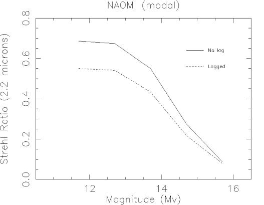
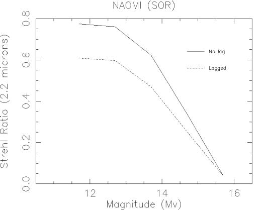
Figure 6: Comparison of on-axis NAOMI performance as a function of reference star magnitude with zonal (SOR) and optimized modal control (A.P.Doel, Durham).
Figure 7: Angular decorrelation for simple zonal correction. The figure shows the 2.2mm Strehl ratio degradation due to off-axis angles for six vertical distributions of turbulence measured by Vernin on La Palma. This is for simple zonal correction where no attempt has been made to optimize for each off-axis angle.
Figure 8: Angular decorrelation for modal correction. This figure shows the Strehl ratio degradation due to off-axis angles for the same turbulence distributions as figure 4. This is for modal correction where the optimum radial degree of Zernike polynomials has been chosen for each off-axis angle. Pupil conjugation is assumed.
Figure 9: Grid illustrating all-sky (top) and galactic latitude > 30° (lower) probability of finding at least one guide star of a given R magnitude within a circular area of a given radius in arcseconds. (Model: Doug Simons, Gemini-Tucson).
3.4.2 Modal Optimisation
3.4.2.1 Introduction
See the section on Modal Control above. Modal optimisation is the process of automatically adjusting modal gains to cope with observing conditions. This technique has been successfully demonstrated by the Adonis and PUEO AO systems both of which use to good effect an optimisation algorithm derived from that described by Gendron and Lena (1995). Modal optimisation is still recognized as having a strong developmental aspect however; particularly in respect of off-axis or field-averaged optimisation or in the use of optimisation selection functions other than minimal wavefront variance over the pupil.
The priorities for NAOMI are the provision of the baseline Gendron-type optimisation and the hooks to allow further extensions. The WHT is well-placed in this respect as the JOSE measurements will provide tests for optimisation techniques and on the frequency of mode gain updates required. It should be note that Adonis and PUEO differ in this respect: the former has an off-line open-loop method and the latter can calculate updates concurrently with closed-loop operation.
3.4.2.2 Specification
|
|
Reference |
Comment |
|
Driving Science
Requirement |
Clauses 2,6 |
Maintenance of high system availability during variable seeing. Improves system stability. |
|
Detailed Specification |
URD |
|
|
Performance Modelling |
See Section 3.4.1 |
on and off-axis benefits of optimized modal control. |
NAOMI will provide the ability to update modal gains on-the-fly whilst the adaptive control loops are closed.
Concurrent calculation of loop gains will take place on a NAOMI workstation. The initial algorithm to be implemented will be as Gendron and Lena (1995).
3.4.2.3 Upgrade
3.4.3 Non-sidereal tracking
3.4.3.1 Introduction
Many solar-system objects will be bright enough for self-referencing. These will be tracked using the tilt off-load capability in which the integrated tip-tilt error is sent to the autoguiding loop. The rate is nominally limited by the autoguiding rate. Faint solar system objects will be followed using the ‘jitter’ facility, which allows motion at up to 4”/sec. This is more than adequate for all known solar system objects (except meteors!).
3.4.3.2 Specification
|
|
Reference |
Comment |
|
Driving Science
Requirement |
Science Clause 7 |
|
|
Detailed Specification |
Optical Chassis WP; FSM WP; Software URD. |
|
|
Performance Modelling |
N/A |
|
3.5 Interface Features
3.5.1 Telescope interface
3.5.1.1 Introduction
A minimal required interface to the TCS will be implemented, sufficient to allow the integrated tilt error to be off-loaded to the telescope autoguiding system. This will adjust the telescope position via a slow feedback loop to keep the integrated tilt error to zero. Focus will also be offloadable to the telescope in order to provide the capability of keeping the WHT wavefront focus peak-to-valley error <0.2 mm. The telescope position and derotator settings will also be available to be attached to the saved data files output by the instrument in use. The interface will be handled by the DRAMA messaging system.
3.5.1.2 Specification
|
|
Reference |
Comment |
|
Driving Science
Requirement |
Clause 4, Clause 7 |
|
|
Detailed Specification |
(Software) URD |
URD currently describes long term goals. It is being modified to reflect baseline requirements. |
|
Performance Modelling |
N/A |
|
3.5.1.3 Upgrade Specification
The software architecture will be designed such that the long term URD requirements can be implemented within the existing architecture. This upgrade would add the capabilities for the AO system procedures to control and co-ordinate all DRAMA-available functionalitity of the telescope and of other instruments AND for AO system functionality to be available to external process such as instrument control and TAG tasks.
3.5.2 Observing interface
3.5.2.1 Introduction
The detailed long term goals for a GUI are described in the Software User Requirements Document. For the baseline system, a GUI will be available which enables user friendly control of the AO system with only minimal interface to instruments or telescope. A DRAMA-based procedural layer will allow efficient internal calibration and control of the NAOMI components through EPICS. The top-level control will be derived from the ELECTRA GUI with minor add-ons found to be high priority from Electra-1 (first light cophasing test of ELECTRA) experience. Control of the NAOMI optical bench will be via a revision of the (editable) ELECTRA optical bench GUI. The project philosophy is that GUI tools are a rapidly changing area of software technology and therefore a full system GUI will be one of the last items to be written and cannot be specified at the present time. It is also envisaged that there will be developments of GUI standards at ING for running the WHT and its instruments. The specifications of these are not yet available, which again drives the decision to provide a minimal GUI based on ELECTRA for the baseline system.
An integrated telescope control - instrument control - NAOMI control GUI would be part of a software upgrade.
3.5.2.2 Specification
|
|
Reference |
Comment |
|
Driving Science
Requirement |
Clause 3 |
|
|
Detailed Specification |
Software URD, FRD. |
URD currently describes long term goals. It will be modified to reflect baseline requirements. |
|
Performance Modelling |
N/A |
Some aspects testable with E0/E1 GUI. |
3.5.2.3 Upgrade Specification
The long term goal is to have a fully integrated NAOMI, Telescope and Instrument interface mitigated by DRAMA.
4. Key Adaptive
Subsystems
4.1 Introduction
The overview of implementation commences with the principal adaptive subsytems:
· Wavefront Sensor
· Tip-tilt Mirror
· Deformable Mirror
· Processing Subsytem
The specifications for each subsytem are introduced and attributed to the driving system-level specifications. References are given to the detailed specification and subsystem workscope documentation. Closely-related ancillary (non-adaptive) features are described briefly for completeness.
4.2 Wavefront sensor subsystem
4.2.1 Introduction
The wavefront sensor (WFS) will use the Shack-Hartmann configuration. In this configuration the input pupil is divided into several subapertures by an array of small lenses. Each lens focuses the light from a guide star on a section of a detector array, e.g. 4 x 4 pixels, and the focused spot's centroid shift is determined by a processor. The average phase gradient for each subaperture is determined by dividing the centroid shift of the focused spot by the effective focal length of the lens. Because the Shack-Hartmann sensor does not provide a direct phase measurement of the turbulence-degraded wavefront, the phase gradients are transmitted to a reconstructor which calculates the phase of the wavefront. Note that both the wavefront processor and reconstructor are part of the RTCS. The conjugate (or reverse) wavefront (with its overall tip/tilt removed) is then applied to the deformable mirror. The tip/tilt information is sent to the tip/tilt mirror discussed in Section 4.3.
The WFS will usually operate with 7.3 subapertures across the WHT pupil. This number defines the system order and it is driven by the science clause 1. System modelling shows that Clause 1 can be satisfied using from 7 to 8 subapertures across the pupil diameter (see
Figure 10 and Figure 11). The segments of the ELECTRA deformable mirror will be optically mapped onto the WFS subapertures. Occasionally the system will operate with a smaller number of subapertures (see section 4.2.2.6).
|
Figure 11: The effect of system order on Strehl ratio at 2.2mm (K-band) for a range of seeing conditions as parameterized by the coherence length ro. (Continuous facesheet DM) |
The main components of the WFS are a pickoff mirror with a field stop, a collimating lens, an atmospheric dispersion corrector (see Section 0), interchangeable lenslet arrays (with ³ 10 x 10 lenslets for the largest array), a relay optic and a CCD. The relay optic images the array of focused spots at the appropriate pixel scale on the CCD. All of these components will be mounted on a remotely controllable stage to allow operation with a guide star anywhere within the 2.9 arcminute field. This stage will also allow jittering to be supported in accordance with Clause 4. The WFS will also have its own calibration source.
4.2.2
Specifications
4.2.2.1
Wavelength
range
The WFS will operate over a spectral range from 0.4 µm to 1.0 µm.
4.2.2.2
Phase
gradient accuracy
The phase-gradient measurement accuracy along any axis will be equal to or better than 0.018 lc rms (where lc = 2.2 µm ) over each subaperture when operating with £ 1500 photons per subaperture per measurement incident upon the CCD when using no more than 4 x 4 pixels/subaperture. This performance includes the effects of sensor noise, photon noise and other sources of error. It is derived from system modelling for the Clause 1 conditions, i.e. system performance with bright stars, and it has been included in the Clause 1 error budget.
When operating with faint stars under the conditions for Clause 2, the phase-gradient accuracy is expected to be equal to or better than 0.14 lc rms (where lc = 2.2 µm ) over each subaperture when operating in the quad-cell mode with £ 40 photons per subaperture per measurement incident upon the CCD. This lower level of performance takes into account the high photon noise present at such low light levels. This performance has been included in the Clause 2 error budget.
Note that the error budgets referenced here are being updated to the 7.3 actuator pupil geometry at the time of writing.
4.2.2.3
Read
noise/ read latency
The WFS CCD will have two readout rates that will be electronically switchable without recabling. There is no need to switch between frames. Under some conditions, e.g. good seeing with low wind speeds, one will be able to use a longer read latency and thus operate the CCD with lower readout noise. At 100 kilopixels/second/port the CCD will have £ 2 noise electrons/pixel and at 1 megapixel/second/port the readout noise will be £ 6 noise electrons/pixel. CCD readout noise and latency have been included in the modelling and the error budgets for Clause 1 and 2.
4.2.2.4
Pickoff
A small (TBD mm diameter) pickoff mirror will direct light from the guide star into the WFS. The pickoff will be an integral part of the WFS and it may be moved anywhere within the 2.9 arcminute field to acquire a guide star. Light passing the pickoff will be directed to the optical science port.
4.2.2.5
Field
stop
A field stop will be provided to allow the use of guide stars in crowded fields. The field stop diameter will be 3 arcseconds.
4.2.2.6
Spatial
descoping
Under some conditions, e.g. low light levels with modal optimisation, a performance advantage may be gained by using fewer subapertures across the pupil diameter; this is known as spatially descoping. The WFS will have the capability to change lenslets remotely to operate with only 4 subapertures across the pupil diameter. This facility is driven by Clause 2.
4.2.2.7
Auto
change of lenslet focal length
A shorter focal length lenslet array will be provided to handle moderate to strong turbulence conditions (r0 < 13 cm). As the atmospheric turbulence increases, the spot excursions also increase. Changing to a shorter focal length keeps the spots on the CCD. This facility is driven by Clauses 2 and 3 together.
4.3 Tip-tilt
mirror
4.3.1
Introduction
As previously stated in Section 4.2, the WFS (or a tip/tilt sensor in a future upgrade) will provide information on overall (or common mode) tilt. This is the tilt present over the entire WHT pupil and it will be corrected by the tip/tilt mirror. There are four sources of tip/tilt error as listed below.
1. Atmospheric turbulence
2. Pointing jitter of the WHT
3. Component vibrations
4. WHT long-term pointing drift
The tip/tilt mirror (a.k.a. the fast steering mirror or FSM) will use the WFS tip/tilt data to primarily correct for the first three sources. The tip/tilt mirror significantly reduces the stroke requirements that would otherwise be placed on the deformable mirror. Large low-frequency tip/tilt errors will be passed on to the TCS to avoid an excessive range requirement for the tip/tilt mirror. The mirror will also serve as a collimating optic, i.e. an off-axis paraboloid, in the common-path optics. This dual function reduces the number of optical surfaces resulting in higher transmission and lower emissivity.
4.3.2
Specifications
The mirror surface will cover an angular range of ³1 mrad over two orthogonal axes. This range is equivalent to about 5.6 arcseconds in WHT object space. The frequency response of the mirror shall extend to TBD Hz at the - 3 dB point. (Current JOSE data from Richard Wilson indicate that 250Hz will be a safe - this will be confirmed for a wider range of conditions within clause 3) The error budgets for Clause 1 and 2 allow for residual rms closed-loop tilt jitters of 0.016 arcsecond and 0.022 arcsecond respectively in WHT object space.
The mirror’s clear aperture of about 100 mm diameter in the current design is large enough to allow conjugation over a 102” field for a dominant turbulent layer at 3 km above the telescope. This matches the effective over-sizing of the DM introduced by having 7.3 sub-apertures across the pupil. However turbulent-layer conjugation is an upgrade and it will not be employed in the baseline system. 100mm is significant because it is the size supported by two potential commercial suppliers of the tip-tilt mirror.
4.4 Deformable
mirror subsystem
4.4.1
Introduction
The deformable-mirror subsystem will correct for the higher-order, i.e. tilt-removed, wavefront errors. Modelling shows that either continuous facesheet or segmented deformable mirrors can satisfy the requirements of Clauses 1, 2 and 3. The baseline system will operate with the 76-segment Electra deformable mirror and its drivers. This mirror has 10 segments across its maximum dimensions and approximately rounded corners. The WHT pupil, as imaged at the mirror, will cover 7.3 segments. The additional segments provide for a future upgrade to a turbulent-layer conjugation capability. Each segment has dimensions of 7.6 x 7.6 mm2. The segments’ optical surfaces are coated with aluminium. Three actuators are used to move each segment thus providing tip-tilt and piston control. The mirror will be provided with electronics to drive the actuators; these electronics are usually referred to as the drivers.
4.4.2
Specifications
The stroke of each actuator is 6 µm. Modelling indicates that this stroke is adequate to handle the strongest turbulence specified by Clause 3 (r0 = 8 cm). Strain gauges and electronics will be provided to measure and correct the hysteresis present in the actuators. The hysteresis will be reduced to £ 0.7% (0.2% currently expected) as required by the results of system modelling with a propagation code. Hysteresis affects both the mirror fitting error (defined below) and the servo system response. The mirror settling time, i.e. the time required for the mirror surface to form a specified shape, will be < 400 µs. An allotment for mirror settling time as part of the system latency has been included in the error budgets for Clauses 1 and 2.
The deformable-mirror fitting error coefficient is a simple way of defining how well the mirror surface matches the conjugate of the turbulence-degraded wavefront. The following equation defines the coefficient.
s2 = µ ( d / ro )5/3
where s2 = variance of the residual wavefront error (radian2)
d = actuator spacing (57 cm projected at WHT pupil)
ro = atmospheric turbulence coherence length (³ 8 cm)
Clause 1 is the driving science requirement for the deformable-mirror fitting error. It is the dominant source of error when operating with bright stars. The error budgets for Clauses 1 and 2 were based on a fitting error coefficient of 0.4 which is characteristic of a well-designed continuous-facesheet mirror. A segmented deformable mirror has a smaller fitting error coefficient (about 0.18) and thus it provides better performance (see Figure 12). This performance improvement was taken into account in recent propagation code studies.
|
Figure 12: Fitting error gains from
linearised segmented adaptive mirror technology. |
4.5 Processing subsystem
The NAOMI computer and software systems are illustrated schematically in Figure 1. The overall software architecture is described in section 9.
|
|
Reference |
Comment |
|
Driving Science
Requirement |
|
|
|
Latency |
Clause 1 |
High bandwidth performance |
|
Modal Control |
Clauses 2, 6 |
sky coverage, system availability and stability |
|
Detailed Specification |
URD,SRD,ADD |
|
|
Performance Modelling |
Figure 6, Figure 7, Figure 8 |
On axis clause 1 and 2 modelling Off axis modelling for zonal and modal control. |


4.5.1 Real-time computer
The real-time computer will perform the three stages of processing required to transform WFS pixel data into mirror figuring commands:
1. The NAOMI real-time computer will accept pixel data from a 4-port WFS camera at at least the maximum peak readout rate and digitization accuracy indicated in the WFS subsystem error budget and specification. These are 1 Mpixel/sec/port and 12 bits/pixel respectively. A peak rather than average readout rate is specified because the WFS will operate in a frame-transfer mode. The first processing stage of the real-time computer will reduce these pixels to subaperture wavefront slope values and will provide for switching its slope estimation algorithm between multi-pixel and quad-cell mode on-the-fly (between one frame and another). The supported WFS readout formats and required phase gradient accuracy are described in the WFS subsystem specification. These are: 6x6 pixels [acquisition-only], 4x4 pixels [WF slope measurement accuracy: 0.018 waves rms at 2.2 microns for clause 1 conditions] and 2x2 pixels [WF slope measurement accuracy: 0.14 waves rms at 2.2 microns for clause 2 conditions]. The algorithm switching will be synchronized with corresponding changes in the WFS camera readout format.
2. The slopes will then be used to derive either a complete set of deformable mirror drive commands directly via a single matrix multiply (zonal control) or a set of instantaneous modal coefficients (modal control).
3. The modal coefficients (if modal control is being used) will then be transformed into mirror drive data. The mirror drive data will then be output via DACs to the mirror power amplifiers.
The elapsed time for all these operations will be £ 250 microseconds between the end of the WFS frame readout and the end of the deformable mirror write operation (but not the DM mechanical settling period). Any relaxation of the overall latency specification (WFS readout + computation + DM settling) will in the first instance be allocated to CCD readout (with a potential read noise gain - see the WFS subsystem specification) rather than to computation.
The real-time computer will provide command and status interfaces which will permit the wavefront correction method (zonal or modal), WFS pixellation and control matrices to be altered and examined. These operations should not cause the control loops to open (in conditions which were otherwise stable).
The real-time computer will make all of its operational data available to an external visualization system where it may be recorded and/or analyzed and subsequently presented. The retrieval of these data for external analysis will in no way compromise the performance of the real-time control computer.
The implementation for the above is described in section 10.
4.5.2 Mechanism control
ING standard methods will be used for the control of all standard mechanized functions (Clause 19).
The baseline is EPICS and VxWorks on a VME-based MVME-167.
Engineering and operational control and status methods will conform to ING standards.
4.5.3 User Interface
A procedural (scripting) interface and simple graphical user interface will be provided for the control of mechanism, real-time, optimisation and visualization functions. Basic visualization functions will be provided.
4.5.4 Upgrade
An upgrade route is available such that a full function GUI and visualization system may be provided which is fully compliant with ING standards.
5. Optical
performance specifications
5.1 Introduction
The optical design of NAOMI aims to fulfil, as nearly as possible, the science clauses in the document Top Level Scientific and Operational Requirements for NAOMI. The givens for the design are
· The WHT optics - diameter, f-ratio, and the position of exit pupil
· The position of the Nasmyth focus 16mm from the edge of the GHRIL optical table
· The GHRIL table - size (1.35 x 2.5 m) and space constraints especially the derotator
· The unvignetted FOV - 2.9 arcmin
· The pixel scale at the science camera - 0.04 arcsec/pixel so as to nearly fully sample the diffraction core of the J PSF.
· The need to minimize the number of warm surfaces in the IR science path to maximize the IR sensitivity. The reductions in background gained by using smaller pixels are easily lost if the emissivity of the AO system itself is too high. See section 5.3.
· The need to maximize throughput to the WFS. The sky coverage of a natural guide star system such as NAOMI is limited by the availability of stars. It is important therefore to make sure that as much visible light as possible reaches the WFS detector.
5.2 Wavelength ranges
5.2.1 IR Science
The operating wavelength range of instruments fed by NAOMI is limited at long wavelengths by the emissivity of the telescope and instrument. Measurements longwards of the K band will have a lower sensitivity because the increased background more than offsets the gain from using smaller pixels. The short wavelength limit of the IR science path is set by the reflectivity of the dichroic which in turn is affected by the need to maximize the visible throughput to the WFS. The reflectivity-transmission curve for the dichroic design being used in modelling is shown in Figure 13. This shows that the mean J band reflectivity is >80% and K-band reflectivity >94%.
|
Figure 13: A dichroic mirror transmission/reflectance curve similar to the one proposed for NAOMI. |
5.2.2 WFS
The wavelength range of the WFS is fixed by the QE of the CCD's, the transmission curve of the dichroic, atmospheric dispersion and the fact that stars at the faint limit of those that can be used as reference objects will be predominantly red (G and later). Taking these factors into account the wavelength range for the WFS is fixed at 0.4 to 1 µm.
5.2.3 Optical science port
For wavelengths shorter than 1 µm (Science clause 3) a new dichroic with high reflectivity at 0.8 µm could be used. This has the advantage of a FOV with no vignetting due to the WFS pickoff but, because of the lower throughput to the WFS, the limiting magnitude on the stars that can be used as a reference will be brighter. Alternatively the dichroic can be removed in which case all the visible light, apart from an area of ~5 x 5 arcsec used for the WFS pickoff, is available at the optical science port.
5.3 IR throughput and emissivity
5.3.1 Introduction
All broad band IR (J filter and longer wavelengths) will be background limited after several tens of seconds on-chip integration, either by OH airglow (J,H) or thermal emission (K,L, M). Narrow band (£4%) filters at wavelengths < 2.4mm will be detector noise limited for most observations because for on-chip integrations of longer than about 5 minutes array and/or sky stability has usually become an issue. This could change as arrays develop. S/N ratio once on-chip integration times have reached background limited conditions varies as the square root of the total integration time. Keeping the emissivity low is important for two main reasons: (a) it improves S/N ratio and (b) the array wells have limited depth so lower background allows either longer on-chip integration times or gives higher dynamic range. At the longer thermal wavelengths the array can saturate even with the shortest possible integration time unless the emissivity is reasonably low. A high IR throughput is a by-product of a low emissivity goal and cannot sensibly be specified independently.
5.3.2 Specification
|
|
Reference |
Comment |
|
Driving Science
Requirement |
Clause 3, 24 |
|
|
Detailed Specification |
Optical Chassis WP doc. |
Drives to silvered surface coatings wherever possible; need to define optimum balance between dichroic optical throughput to WFS and K-band emissivity |
|
Performance Modelling |
AJL IR simulation. See Figure 3 for an example |
Sensitivity to point source simulated by assuming 0”.2 effective seeing. Expected to be accurate to 25%. Simulations using real AO-generated psfs in progress |
5.4 Optical throughput
5.4.1 Introduction
The optical throughput driver is therefore to get as many photons to the WFS as possible (Clause 2) and also to meet the optical science port throughput requirement (Clause 9). This is jointly met by minimizing the number of surfaces and making an optimum choice of coatings. The balance of dichroic coating between maximum optical transmission and maximum IR reflectance (minimum emissivity) presents a direct conflict. The NAOMI system philosophy is that sky cover is very important while a change in the emissivity of one surface from 3% to 6% makes negligible difference to the S/N ratio obtainable at IR wavelengths given the overall system emissivity. Therefore Clause 2 becomes the main driver for the optical throughput of the dichroic. The dichroic coating currently assumed (see section 5.2.1) has the 50% transmission/reflectance cross-over at ~0.8mm.
5.4.2 Specification
|
|
Reference |
Comment |
|
Driving Science
Requirement |
Clauses 2, 9 |
|
|
Detailed Specification |
Optical chassis WP |
|
|
Performance Modelling |
MW system throughput |
See below |
The table below shows the integrated throughput (in percent) from 0.4 to 1mm at the WFS for guide stars of different spectral type. The model includes the reflectivity of all telescope and NAOMI mirrors, all the air-glass interfaces, the expected QE curve for the EEV CCD and the dichroic transmission curve shown in Figure 13
|
Spectral type |
O9 |
B0 |
A0 |
F0 |
G0 |
K0 |
M0 |
M5 |
|
Mean throughput - With dichroic |
18 |
28 |
27 |
25 |
23 |
23 |
19 |
15 |
|
Without dichroic |
34 |
34 |
33 |
31 |
30 |
29 |
25 |
22 |
The next table shows the same information but for a wavelength range from 0.5 to 1mm and includes the expected number of detected photons for a 16th magnitude star. Viewed together with the sky cover figures this demonstrates that the proposed system meets Clause 2 of the specifications.
|
Spectral type |
O9 |
B0 |
A0 |
F0 |
G0 |
K0 |
M0 |
M5 |
|
Integrated detection rate |
|
|
|
|
|
|
|
|
|
With dichroic |
29% |
29% |
27% |
25% |
23% |
22% |
18% |
15% |
|
Without dichroic |
36% |
35% |
33% |
31% |
29% |
28% |
25% |
22% |
|
Detected photons† |
|
|
|
|
|
|
|
|
|
With dichroic |
40 |
40 |
28 |
32 |
34 |
37 |
70 |
155 |
|
Without dichroic |
48 |
48 |
34 |
41 |
44 |
49 |
97 |
228 |
† Photons/sub-aperture/25 msec, spectral bandwidth 0.5-1 µm, detected by the WFS CCD for stars of these spectral types with mv=16
5.4.3 Upgrade Specification
The field delivered to the acquisition TV is the full unvignetted field the telescope passes through the derotator, but with some obstruction of the pupil by the WFS (and possibly TTS) pick-off mechanisms. With an upgraded acquisition camera it will be possible to carry out some simultaneous IR (approx. >1mm) and optical (approx. <0.8mm) scientific experiments with an AO corrected image.
5.5 FOV; Image quality; correctable and uncorrectable errors
The FOV of the IR science port is fixed by the size of the dichroic mirror. In the baseline design the FOV is 15 arcsec diameter which matches to WHIRCAM with 0.04 arcsec/pixel. A 10242 instrument (FOV 1 arcmin, Science Clause 7) can be accommodated with a suitably sized dichroic coating area.
The system is diffraction limited at J and longer wavelengths, in the absence of atmospheric and telescope aberrations, over this 1 arcmin FOV.
At the larger off-axis angles used by the reference stars there are significant aberrations introduced by the telescope and AO optics. These aberrations will produce offsets in the WFS which have to be subtracted before the modal decomposition is carried out. The stability requirement (Section 5.6) means that these non common path errors should not change during an observation.
5.6 Stability
The system will be designed such that the performance specified in Clauses 1, 2 and 3 is achieved for integrations up to 1 hour, without recalibration, provided the telescope alignment and focus stability is adequate for this. This requirement is driven by Clause 5.
6. Opto-mechanical
system design requirements and goals
6.1 Introduction
The constraints and requirements on the optical design of NAOMI are given in section 5.
A diagram of the layout is shown in Figure 2. This shows the principle components and their relationship to the derotator and the GHRIL optical table. A brief 'walk through' description of the system is given in Table 1 and a more detailed list of all the components is given in section 8.
|
The f/11 beam from the derotator reaches a focus 16mm after the edge of the existing GHRIL optical table. The unvignetted FOV is 2.9 arcmin in diameter. |
Nasmyth f/11 focus |
|
Light from the alignment system can be injected into the main optical path by inserting the alignment beam splitter in front of the f/11 focus. |
Alignment system |
|
A camera is placed opposite (in an optical sense, not necessarily physically opposite) the alignment beam. This allows a comparison to be made between the 'before' and 'after' correction images. |
Alignment camera |
|
From the focus the beam is collimated by the off-axis paraboloid (FSM) which also acts as the fast steering mirror of the system used to remove the tip-tilt component of the incoming wavefront. The FSM images the telescope exit pupil on to the DM. |
FSM |
|
The full 2.9 arcmin Nasmyth FOV is refocussed by OAP2. The focal length of OAP2=1.5 focal length of FSM giving an f/16.5 corrected focus. In front of the second focus an IR reflecting dichroic beam-splitter spectrally separates the IR/science and optical-WFS paths. |
OAP2 |
|
The field lens just in front of the optical path focus makes the system at this point telecentric (DM imaged at infinity). This is required so that when selecting off-axis guide stars there is no movement of the image of the DM at the lenslet array. |
Field lens |
|
The guide star is selected by moving a small mirror in the focal plane. The mirror directs light from the star towards the WFS. Note that the whole WFS assembly has to move with the pickoff. |
Guide star pickoff |
|
The pickoff mirror is mounted on a thin glass disc which allows the rest of the 2.9 arcmin FOV through to the acquisition camera and any optical instrumentation that is to be used with NAOMI |
Acquisition camera |
|
A collimating lens in the WFS path images the DM onto the lenslet array. The collimated space between the collimator and the lenslet allows for the insertion of the WFS ADC. |
WFS collimator ADC Lenslet array |
|
The array of spots produced by the lenslet array is imaged onto the CCD detector with an focal reducing relay lens (not shown in diagram) |
WFS relay lens |
6.2 IR Science Port
The IR science port has a FOV limited initially by the dichroic beamsplitter. In principle it can be up to the full 2.9 arcmin available at the Nasmyth focus, but the telescope/instrument PSF will not be diffraction limited beyond about 30 arcsec from the optical axis at 1.2 µm (J-band). The following numbers are nominal values. Actual designs of IR instruments will need to use the as-built values and a full ray-trace.
The f/ratio is 16.5.
The plate scale is 335 µm/arcsec
The image of the telescope pupil is at a distance of 1100mm beyond the focus and has a diameter of 66.7 mm.
The footprint available for IR instrumentation is TBD
6.3 Optical Science Port
The optical science port has a FOV of 2.9 arcmin.
The f/ratio is 16.8
The plate scale is 338 µm/arcsec
The image of the telescope pupil is at infinity. i.e. the system at this focus is telecentric.
The footprint available for optical instrumentation is TBD.
6.3.1 Acquisition Camera
An acquisition camera will be provided at the optical science port. Initially a low cost CCD video camera will be used. The camera will have a nominal pixel scale of 0.45 arcsecond/pixel. The video camera should be able to detect stars with V³8. The choice of camera will be driven by cost and availability. It will cover the full 2.9 arcminute field in at least one axis. A possible alternative to the video is the use of an ING autoguider CCD. This possibility is currently being investigated.
As part of a system upgrade, it may be replaced by a copy of the Gemini acquisition and HRWFS camera, most probably using the 1024 x 1024 pixel EEV47 CCD. This camera will operate with a smaller pixel scale (0.17 arcsecond/pixel),view fainter stars (V>26) and allow detailed inspection of a limited area (£256 x 256 pixels) at ³10 frames/second.
7. Alignment and
Calibration
7.1
Introduction
Two sources are required at different locations for alignment and calibration purposes. Provision will be made to insert remotely a point source at the f/11 Nasmyth focus at any location within the field using an x-y translation stage. A second point source will be located off axis at the corrected f/16.8 focus to provide a diffraction-limited input wavefront for WFS calibration. It will be positioned just outside the 2.9 arcminute field but within the range of the WFS pickoff stage.
7.1.1
Specifications for
the Nasmyth calibration source
This source will perform several functions:
a. Provide radiation over at least the 0.5µm to 2.2µm spectral region for use by the WFS, the acquisition camera and science instrumentation, e.g. to boresight these components; to calibrate the common-path and non-common-path wavefront errors.
b. Simulate the WHT exit pupil, e.g. as an alignment aid for determining the deformable mirror position and for minimizing the difference between laboratory calibrations and sky.
c. Map the AO system distortion over the full field for astrometry purposes. The repeatability of the mapping operation will be £ 0.01 arcsecond.
d. Introduce small (£ 2.6 arcsecond, frequency <150Hz) motions of the source for functional checks of the AO control system.
e. Uniformly illuminate the f/11 beam so that when a pupil of the system is imaged on to the WFS detector each pixel receives the same signal. This requirement follows from the need to flat-field the WFS detector.
7.1.2
Specifications
for WFS source
The source may be positioned anywhere within the WFS field of view to allow generation of WFS transfer curves, i.e. plots of measured phase gradient versus actual phase gradient. The maximum source brightness will be equivalent to at least a magnitude-8 star representative of Clause 1 conditions and the brightness may be decreased by either a factor of 10 or 100, as desired, to simulate fainter stars. The source spectral bandwidth will cover 0.4 µm to 1 µm.
8. Global Opto-Mechanical Components
The following table lists all the opto-mechanical components of NAOMI.