
Royal Greenwich Observatory,
Madingley Road,
Cambridge CB3 0HJ
Telephone (01223) 374000
Fax (01223) 374700
Internet gtr@ast.cam.ac.uk
WHT-NAOMI-12
Design Study for an
Observing System
Incorporating NAOMI
Guy Rixon
Issue 2.1; 1997-02-04

Royal Greenwich Observatory,
Madingley Road,
Cambridge CB3 0HJ
Telephone (01223) 374000
Fax (01223) 374700
Internet gtr@ast.cam.ac.uk
Document history
Issue 1.1- 1996-12-23 Original text.
Issue 2.1 1997-02-04 Significant changes in content: the `tracker camera' is no longer included and the coupling of the `ING system' to Electra is revised. The Electra D-task is now a necessary part of the initial system.
This is a an outline design for the observing system, written for the internal use of the AO project. Instead of trying to design the detail of the AO controls (which is in case impossible with the available information), I have concentrated on how the assemblies built to be built by the NAOMI and Electra projects can be fitted into an existing observing-system. Concepts are more important than tangible details.
The document is structured as an architectural-design document defined by PSS-05. Sections for which no information is available, or which do not seem to need explaining to the current audience, have been left blank.
For a new and ill-defined subject like AO, a careful analysis of the user requirements is essential to reduce the risks of project failure. No analysis, other than the informal one I carry in my head, has been undertaken; the design presented below is only as valid as the assumptions that I have based it on. I have tried to make those assumptions explicit in the commentary, but there will undoubtedly be others that are not stated. Hence, do not trust this model to be correct and valid. We can learn much from discussing it, but it would be insane to commit money to the design in its current state.
1.2 Scope of the software
The WHT observing system is the totality of all the software that needs to run to allow observing on the WHT. It has a controls part, concerned with telescope pointing, instrument control and acquiring data to disk, and a data-handling part concerned with logging and archiving the observations. This document is concerned only with the controls side and ignores data handling.
The AO-specific targets in the control system are the deformable mirror (DM), the fast-steering mirror (FSM) and, separately, everything else on the NAOMI optical bench.
Non-AO targets for control are the telescope and the science detector. No other instrumentation is considered here.
1.3 Glossary
These are semi-standard terms for parts of the existing ING systems.
CIA (yes, Central Intelligence Agency; what else?) means the DRAMA-based programs that coordinate actions on various server programs. The CIA centralizes high-level control of the distributed system and is constructed from a set of agent programs also known as transient clients.
Transient clients are programs that encode the logic for one or a few user commands. Such a client is started as a sub-process by some user interface, executes its command and then exits.
DAsS is the data-acquisition sub-system: the group of programs that record observations on disk. It does not include the detector-control software.
DRAMA is AAO's structure for building communicating real-time programs. It defines both the inter-process messaging and the structure of the participating programs.
Resident clients are programs that run for as long as the observing system is loaded and which make transactions with the server programs. Most resident clients are GUIs.
Electra is, of course, both a complete and self-sufficient system
and project independent of NAOMI. I have consciously misused the name Electra
in this document to mean `the part of the Electra system that is reused
in NAOMI' firstly because I wanted to emphasize the origins of that equipment
and secondly because I couldn't think of anything else as concise. The NAOMI
project should perhaps think of another term that is less open to confusion
and less demeaning to the Electra project.

The deformable mirror (DM) will be inherited from the Electra project because the NAOMI project has insufficient funding to design its own. To save money, the design must re-use as much of the Electra product as possible, including Electra's computing arrangements.
The rest of the AO equipment must be controlled by computers and programs supplied in the NAOMI project. The controllable mechanisms are:
z fast-steering mirror (FSM);
z wavefront sensor (WFS), to be interfaced to the DM and FSM;
z assorted mechanisms for alignment and calibration which don't need to be considered separately at present.
The telescope control system and the DAsS will be inherited from the existing ING observing systems. They will embody ING's normal client-server architecture based on DRAMA and may not be greatly changed to suit NAOMI. Since the project has little money, it must reuse as much as possible of the ING system.
The science detector will be an infra-red array whose camera and controls will be produced in a parallel project. The detector's computing arrangements will follow ING's conventions not Electra's.
For the various things controlled, I have grouped all the signals into outgoing `demand' and incoming `telemetry'. On the context diagram, each of these flows is composite. The exact details of the external interfaces do not concern the current study.
There are several cameras in the system, each producing pixilated images. I have shown the images as flows of analogue pixel-values (`APV' in the flow names) because the digitizing stage for these cameras is inside the system.
The user console is the point from which the system is controlled. It is intended to be some device supporting X-windows. There is a user-requirement that the system be fully controllable from one console, but it in the nature of X-windows that particular interfaces may be distributed to any supporting device won the appropriate network. The fast visualization graphics will most probably be available only on the system console of an SGI workstation (this function requires special support in hardware). In this case, it must be possible to bring the rest of the user interface onto that machine.
3.1 Definitions of external interfaces
Data for this section is not available yet.
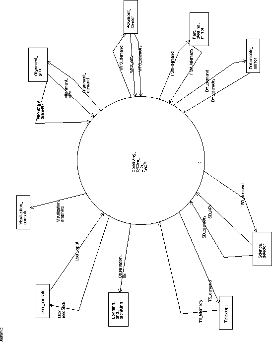
The system is decomposed by Hatley and Pirbigh's method, which resembles Yourdon's method for structured analysis in its treatment of data flows. The method is used rather loosely and there is no rigorous representation of control semantics.
The design choices reported here underlie the costing model for NAOMI software-development proposed by Gentles and Rixon.
4.2 Decomposition of the system
4.2.1 The first division.
There are a number of ways to make the first division of the system. Since the AO system seems destined to be a patchwork quilt of inherited programs, I have chosen to divide by origin, rather than by function, data ownership or processor.
On the left, in the figure below, is the partial system produced by RGO and ING. It can drive the telescope and science detector by itself, and has user-interfaces to do so. This half-system also includes the low-level controls for the `slow' AO mechanisms: that is, those devices not generating or receiving data at high bandwidth. This half of the system could be used in isolation for `classical' observing but it cannot close any of the adaptive-optics loops because it has no control of the DM or FSM.
On the right is the equipment inherited from the Electra project. It is the rump of a complete AO system in which the DM is retained and the FSM and WFS are replaced by new items supplied in the NAOMI project. The controls for the fast mechanisms are also inherited from the original Electra. This new, partial incarnation of Electra can complete the crucial AO-loops but is not a complete AO system by itself as it does not have full control of the WFS' carriage, the telescope or the science detector.
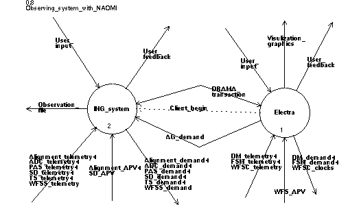
In this diagram, the flows WFS_telemetry and WFS_demand from
the context diagram have been broken up: Electra handles the fast manipulation
of the CCD camera

and the ING side handles the WFS support-carriage. The WFSC prefix
refers to the camera and WFSS to the support carriage.
Both Electra the stand-alone experiment, and the existing ING observing-systems
have three-layer structures. There is a (G)UI at the top, and a server
layer at the bottom. These are connected by a central intelligence layer.

Clearly, most operations have to coordinate actions in both sides. There are broadly three approaches:
(i) Make the ING-side mechanisms directly accessible to Electra at some low level of control. Discard ING's central intelligence and user interfaces.
(ii) Make Electra's real-time control of the DM directly accessible to the ING-side system. Discard Electra's central intelligence and user interfaces. (Keep Electra's visualization system but make it output only and not part of the system's general GUI.)
(iii) Retain the basic user-control and display of mechanisms in their own halves of the system. Make only sufficient changes and connections for the necessary exchange of data and sparse control-signals.
Option (ii) has similar costs to option (i) since it has to replace all of Electra's command-sequencing and scripting logic. The usefulness of the visualization console is likely to decrease. Making these changes may be difficult without staff trained in Electra's computing environment.
Option (iii) is the cheapest almost by definition. It is clearly not how one would design a system if there was no legacy equipment to consider, since it requires maintenance of two radically different technologies. However, since the NAOMI project has no money for consolidating the technology, option (iii) is only one that is affordable without risk - if there is a way to implement this option. The rest of the design presents one such way that has potential to evolve from an option-iii system to an option-ii system if extra funds become available.
In order that the merged system can be evolved towards ING norms, the link between Electra and the ING system is made with DRAMA technology. The next section explores how this works on the ING side as an introduction to how Electra's control-link can be made.
4.2.2 ING command and control
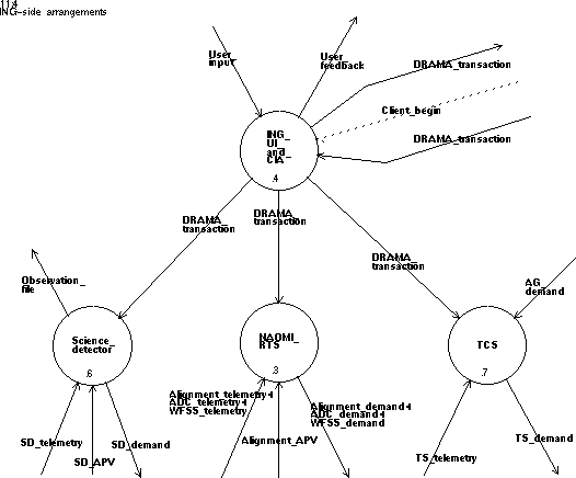
This diagram shows the basic structure on the ING side. The top-most bubble includes the user-interface programs and the central intelligence. It turns the users' commands into sequences of DRAMA transactions on the three sub-systems in the bottom rank (I have put science-detector control together with the DAsS). The three sub-systems are independent and all coordination passes through the CIA. The off-page flows pointing to and from the upper right-hand side are links to Electra. Most of these are low-bandwidth connections to the ING CIA using DRAMA. The exception is the dedicated link from Electra to the TCS carrying autoguider signals. This is the standard kind of serial connection used by ING autoguiders.
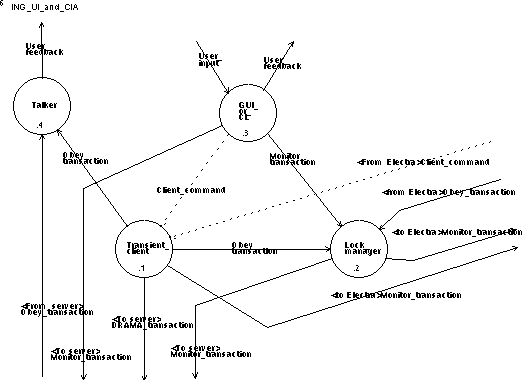
Inside the top half of the ING system, we have the processes shown in the diagram above. All are DRAMA tasks, linked by the DRAMA message-net.
GUIs are Tcl/Tk programs using AAO's extensions to Tcl to monitor DRAMA parameters in the ING real-time sub-systems: this mechanism drives the mimic diagrams. The ING system uses a normal Unix shell as a command-line and scripting interface.
The transient client represents one user command in progress. It is a separate program which embodies the sequence of action in that command and is started by one of the UIs. Each client ends - the process exits - when the command is complete. Clients can be killed prematurely by the UIs to shut down unwanted commands.
The Talkers (there is one per workstation in the system) are messages displays. When clients or servers needs to send messages to the user, they do so by starting DRAMA transactions on the talker. Despite its position in the system diagram, and despite have a graphical interface, a talker is a server program.
The lock manager tracks the state of the system and acts to block some user commands. Clients make requests, as obey transactions, to the lock manager to execute their commands; the lock manager gives its verdict in the status message of the transaction. The system state is deduced from the set of locks held by extant clients and from a set of state variables in the DRAMA servers that the lock manager monitors. The GUI programs monitor parameters in the lock manager to get a continuous reading of which commands are cleared for use.
4.2.3 Connecting Electra

In the previous two diagrams, the flows to and from the top left are the connection between Electra and the ING system. Electra makes action requests by starting and stopping clients as if it were one of the ING UIs. In this way, the AO system inherits all the client code already written for the WHT. A few special clients will be needed for AO operations, but basic facilities such as slewing the telescope to a new target can be used without change and without disabling the ING UIs.
In order that commands to the two system halves not interfere with each other, Electra is extended to use the ING lock manager; this happens in three ways.
Firstly, locks are acquired and released by ING-side transient clients. If Electra starts an action in the ING-side equipment, for example an exposure on the science detector, then it does so by invoking a client. The client obtains the `clear-to-expose' lock and, in so doing, sets up the necessary interlocks. When the client exits, the lock is released and the interlocks are cleared.
Secondly, Electra provides a set of DRAMA Boolean parameters (e.g. `is the WFS-DM loop locked?') that the lock-manager monitors. In this respect, Electra is behaving like any other DRAMA server.
Thirdly, if Electra needs to initiate some internal action that may be interlocked, it asks for the lock directly from the lock manager. That is, Electra may need to behave as an ING-side client.
The next diagram shows an outsider's view of Electra with its added DRAMA interfaces. The UI section, a real-time control section and a central intelligence are shown, all linked with Electra's private messaging protocol. None of these parts need to change significantly, but the CI must be adapted to talk to a pair of DRAMA processes.
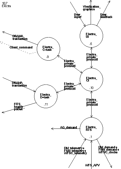
The Electra C-task is capable of starting (and stopping) ING client programs
to get access to the ING-side mechanisms: it does this in response to specific
commands from the Electra CI and so needs no intelligence of its own.
Some of the interlocking of operations is activated for Electra by the clients
it invokes. To interlock its internal operations against ING-side events,
the Electra C-task makes direct obey-transactions to the lock manager.

In the first version of the system, the Electra D-task exists only to serve DRAMA parameters to the ING-side mechanisms. It is not a means by which the ING-side interfaces can control Electra and the parameters are read-only.
The parameters have three uses:
(i) Boolean state-parameters (e.g. is the WFS-DM loop locked?) are monitored by the lock manager and drive the interlocking;
(ii) mechanism-demand parameters (e.g. desired value of telescope focus) are monitored by transient clients and used to close the slow servo loops;
(iii) sub-system-description parameters (e.g. current Streyl ratio) might be used to drive the logging functions in the DAS.
In later revisions, a DRAMA action interface might be added by which some of the Electra functions can be invoked from outside.
Initially, it will be easiest to route these action requests through Electra's CI. However, given sufficient interlocking elsewhere in the system, some of the action requests could be routed directly from the D-task to Electra's real-time controls. In this way, the ING CIA and UIs can gradually take over the work of the Electra CI and UIs until eventually only the real-time part of Electra remains.
This migration need only take place if a definite gain in use of use or maintenance costs can be demonstrated. The migration, and hence the D-task, are not needed to complete NAOMI.
Logging of Electra's state can be driven either by the parameter interface described above or by an action in the Electra D-task. In the latter case, the action indicates to Electra the beginning and end of the science exposure and causes a FITS-header packet (i.e. a file of FITS descriptors) to be written where the DAS can find and read it. This is the preferred method for the rest of the ING systems and avoids the need to publish to much of Electra's state in the parameter interface.
4.2.4 AO controls on the ING side.
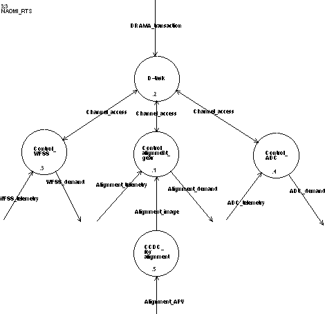
The controls for the NAOMI optical bench are a combination of EPICS and DRAMA. EPICS is required for the ease with which low-level control operations can be programmed. DRAMA is used as the link to the CIA and UI.
If possible, EPICS layer should be a single database, as this requires least hardware. It may be necessary to split the EPICS code into two or more databases, possible running in more than one VME crate, but this does not greatly affect the usage of EPICS by the greater system. In the diagram above, the processes in the middle layer comprise the database.
The D-task is intended to run in the EPICS VME crate. If there are multiple databases, then they shall have one D-task each. Normal communications with the EPICS crate(s) use DRAMA's networking protocol which is layered on TCP/IP and the telescope LAN. DRAMA to EPICS communication is by EPICS' Channel Access protocol running on a single processor and address-space.
The arrangement of DRAMA and EPICS in the same crate is not the only possible solution, but it is likely to be the cheapest and most effective. Two other possibilities have been examined.
It is possible to move the D-task out of the crate onto the system-coordination computer. This has two `advantages': the inter-processor link uses EPICS `superior' networking code (if one believes that Channel Access is and will remain superior to IMP, DRAMA's messaging system); the developers of the EPICS and DRAMA layers can code and test independently. I believe that both advantages are false for the following reasons:
z I see nothing inherently superior in Channel Access when compared to IMP, except that IMP is currently less well debugged. ING will have to obtain a reliable version of IMP in any case, and must do so well before the end of NAOMI coding.
z Separating the development of the D-task and EPICS database, as has been done for the D-task and 4MS pairings in previous WHT instruments, is a false economy. The two teams tend to make different assumptions and work to different paradigms, and the integration of the sub-system is ultimately much harder. The D-task developers cannot, in any case, test their task independently of the database unless they write a simulator for the EPICS crate.
z The D-task reports much of the EPICS database's state upward to the CIA: that is half its purpose. The reporting is through DRAMA parameters, which means that the D-task is recording the state. If the D-task and database are on different processors then the D-task's record of the database's state can get stale due to communications problems, but this staleness is not obvious to the D-task's clients. In particular, one needs to handle the case where the D-task is running and the EPICS crate is goes off-line for some time and then comes back on-line. This is an excellent way to complicate the communications.
It is also possible to do away with the D-task and connect the database directly to the CIA and UI using channel access. This is technically feasible but is likely to be expensive:
z The support library for CIA would need new functions to let the transient clients use channel access. Some clients would need both IMP and channel access.
z The GUIs on the ING side of the system would have to deal with both EPICS and DRAMA communications. This prevents us from using the generic Tcl interpreter supplied by AAO and forces us to write our own, specialized interpreter.
With DRAMA communications to the EPICS crate, the channel-access links can be used as a cheap, back-up system for debugging when the database and D-task are integrated.
It is not sensible to attempt a detailed description of the arrangement of the database at present. Instead I note that the mechanism groups shown seem to be independent at the EPICS level. I have drawn them as separate processes with separate channel-access communications. Each of these groups clearly contains multiple EPICS records with interconnections. This establishes the principle that interactions between mechanism on the optical bench should be handled in the database, not in the D-task. This choice is made on the assumption that inter-record links in EPICS are easy and cheap (in programming time) to set up, whereas cross-links in DRAMA are hard work.
The alignment group has the use of a CCD camera and frame-grabber. I have drawn the CCD controller as a separate (non-EPICS) device as I do not know of any EPIC-enabled controllers. The interface between the controller and the EPICS database needs to be determined and will probably be dictated by the type of controller chosen.
4.2.5 Science detector and data acquisition
Details of this will be added in a later issue of the ADD.
4.2.6 Telescope control
The existing TCS will be used. This system runs on Alpha/VMS

and includes a D-task for inter-processor communications. Autoguider signals
- periodic reports of a guide-star position from which the TCS computes tracking
adjustments - are accepted over a serial cable. Details will be added in
a latter issue of this ADD.
4.3 Check-list of AO control-loops
This is the list of control loops from issue 3.1 of the software URD with notes on how the loops can be implemented in the proposed architecture.
WFS-DM: The data source, data sink and initiation of this loop are all contained within Electra. Electra should probably check with the lock manager before starting or stopping this loop.
DM-TCS: (the loop that tunes the telescope's focus) The data source is parameters in the Electra D-task. The data sink is the action interface of the telescope D-task. The loop is closed by starting a transient client that invokes the focus action for each change in the relevant parameter. The loop is opened by killing off the client. The rate of updates is likely to be limited by the speed of reaction of the focus drive; the DRAMA communications should take only milliseconds to pass each update.
Optimization: this is done inside Electra if it is done at all.
WFS-FSM: this loop is entirely within Electra, as for the WFS-DM loop.
TTS-FSM: this loop is not catered for as the tip-tilt sensor has been dropped from the project.
FSM-TCS: excess FSM movement is converted by Electra to changes in x-y position of a hypothetical guide-star. The guide-star positions are fed to the TCS over a serial cable as if a standard ING autoguider was in use. Update rates up to about 2Hz are possible.
WFSC-WFSS: (the loop that keeps the guide star centred in the WFS) is implemented by a transient client monitoring demand-parameters in the Electra D-task and invoking an action on the optical-bench D-task. The DRAMA communications should support adjustment rates up to about 20Hz and possibly faster.
WFS self-focus: is one axis of the WFSC-WFSS loop.
TCS-ADC: zenith distance is available as a parameter of the telescope D-task. The loop is closed by a client program that monitors the parameter and relays the datum to the EPICS database via the optical-bench D-task. The conversion from zenith distance to ADC demand position is done in the database. The loop is opened by killing the client.
The maximum update-rate of a loop closed by a DRAMA client may be limited by the speed of the messaging. DRAMA messages on a single computer take a minimum of about 1 ms to arrive and each parameter-update/obey-action cycle involves four such messages. I expect that cycle rates of up to 20 Hz are possible, but this should be proven by experiment. I do not know the speed of channel-access messages.
The TCS currently runs its fastest calculations at 20 Hz.