Tip/Tilt Sensor Work Package
Description wht-naomi-101
Document Number
AOW/SUB/RAH/1.6/04/96
Changes from previous
version are generally indicated in italics. The changes in this version are
minor. They include changes for consistency with other work packages, minor
editorial changes and updated document references.
1.0 Introduction and
General Requirements
This document should
be read in conjunction with the WP Cover Document AOW/GEN/AJL/6.4/03/96 which
references several other relevant documents. Together these documents
constitute the current requirements for the WHT NGS system. (These documents
are from time to time updated by their authors; readers can ensure they have
the latest versions by checking with the Project Manager.)
1.1 Introduction
The primary activity of this work package shall be to design, build and test a tip/tilt sensor for the WHT NGS AO system. This tip/tilt sensor, together with a fast steering mirror (FSM), will usually operate as a closed-loop subsystem. In this mode the tip/tilt sensor/FSM subsystem provides a tilt-stabilised image to the system’s wavefront sensor. The capability to operate occasionally as an independent closed loop system is also required, i.e. to provide only tip/tilt correction. A secondary activity will be to consider approaches to more advanced tip/tilt sensors, particularly infrared designs; further information is provided later in this document. The latter activity will involve a relatively small amount of effort.
Although the wavefront sensor can perform the tracking function in a natural guide star AO system, there are several reasons for a separate tip/tilt sensor for the WHT NGS system as summarised below.
a) The design must not preclude future operation with laser guide stars; a laser upgrade is planned for the WHT. A laser guide star does not provide tip/tilt information and thus a tip/tilt sensor must be used to obtain this information using a natural guide star.
b) The optical design will allow the use of separate guide stars for tracking and wavefront sensing. There are two potential advantages to be utilised when separate guide stars are available. First, the tilt isoplanatic angle exceeds the isoplanatic angle (typically by a factor of about 3) and thus one has a larger guide-field diameter for tracking stars than for higher-order wavefront sensing. Second one does not have to share light with the wavefront sensor and thus one can operate at higher signal to noise ratios.
c) A stabilised input image to the wavefront sensor facilitates the loop closure. The stabilised input image is particularly important when the need arises to operate the WFS CCD in a quad-cell mode to reduce readout noise, e.g. when operating with very faint guide stars. The useful tip/tilt range of a quad cell is, of course, limited by the image size.
The tip/tilt sensor-FSM subsystem must correct for the three sources of tip/tilt error given below.
1. Atmospheric turbulence
2. Pointing jitter of the WHT
3. WHT long-term pointing drift
The tip/tilt sensor will measure the combined effect of all three error sources. The fast steering mirror will primarily correct for the first two error sources; any small-amplitude, high-frequency residual error will be passed on to the wavefront sensor and deformable mirror. The FSM significantly reduces the stroke requirements that would otherwise be placed on the deformable mirror. To avoid an excessive range requirement for the FSM during long observing periods, the long-term pointing drift will be corrected by feeding low-bandwidth or DC tip/tilt sensor error signals to the WHT control system. The unguided tracking accuracy of the WHT1 is given as < 1 arcsec (4.8 µrad) over 10 minutes; this figure indicates the magnitude of the potential long-term pointing drift.
The tip/tilt sensor will utilise the light from a natural guide star. The wavelength region of the guide-star radiation depends on the location of the guide star within the field of view (see Sections 1.1.4 and 1.1.6 of the Optical Chassis Work Package Description AOW/SUB/RAH/4.4/04/96.) If the guide star lies within the science-instrumentation field, the tracking wavelength region will be restricted to 0.5 µm to 0.8 µm. If the guide star lies outside the science field wavelengths longer than 0.8 µm will also be available. In the near term a tip/tilt sensor with useful response up to at least 1 µm is desired.
The tip/tilt sensor design must use existing low-risk technology in a cost-effective manner. The tip/tilt sensor designer must be fully cognisant of the tip/tilt sensor-FSM subsystem requirements and its interfaces with the Real-Time Control System (RTCS) and the Telescope Control System TCS).
1.2 Measurement accuracy
The residual sensor error produced by photon noise and other tip/tilt sensor error sources shall be < 50 nrad rms (0.1 arcsecond rms, each axis, one sigma in object space) when the adaptive optics system is providing essentially diffraction-limited correction at 2.2 µm and the tip/tilt sensor is operating with light of wavelength = 0.65 µm. An atmospheric coherence length of 20 cm at a wavelength of 0.55 µm shall be assumed for this specification which is derived from the Clause A error budget discussed later in Section 3.0. The tip/tilt sensor design should allow the specified performance to be achieved when operating with 300 incident photons per dwell time in the input beam. The minimum tip/tilt sensor dwell (integration) time has yet to be determined for the WHT site as part of the JOSE programme; the dwell time may be only a few milliseconds under worst case conditions.
In the tip/tilt (or stand-alone) mode the tip/tilt sensor will operate with an uncorrected star image probably subtending between 2 µrad to 7 µrad diameter ( approximately 0.4 to 1.5 arcsecond). Under these conditions the residual tracking jitter should be less than 0.1 rms of the time-averaged image diameter.
1.3 Acquisition range
The tip/tilt sensor shall have an acquisition range of at
least ± 12 µrad (± 2.5 arcseconds) in WHT object space over each axis.
1.4 Intensity range
The tip/tilt sensor shall operate over an intensity range of at least 10,000 to 1; the use of
neutral density filters to achieve this range is acceptable. If such filter are used they shall
be remotely
interchangeable via the RTCS.
1.5 Focus-sensing capability
If a
focus-sensing capability can be provided (subject to the conditions given in
Section
2.1 ) then it
shall sense focus changes to an accuracy of 0.1 wave peak-to-valley at a
wavelength of 0.7 µm. The bandwidth of this capability will be specified when
sufficient data are available from the JOSE programme. It is expected to be
very low. If focus sensing is not provided for the near-term tip/tilt sensor
this specification becomes a requirement for the advanced tip/tilt sensor.
1.6 Tip/tilt sensor output signals
The tip/tilt sensor supplier shall supply only intensity signals from the tip/tilt sensor detector(s). The format of these signals is TBD. The signals will be fed to a pre-processor which converts these signals to image-position data for input to the RTCS. Considerable interaction is expected between the tip/tilt sensor supplier and the RTCS supplier. The programme will supply a simpler version of the pre-processor for checkout and testing of the tip/tilt sensor. This simpler pre-processor will perform all functions considered essential for a laboratory demonstration. The remainder of this section is provided for information purposes only.
The tip/tilt sensor pre-processor shall provide at least two sets of digital output signals for external use. One set is the low-bandwidth signals used to correct for the long-term pointing drift of the WHT either at a 1-Hz update rate or integrated over a longer (selectable ) period (< 1 minute). The second set provides the drive signals to the FSM. The capability to transmit all signals over a 100-m cable path to the WHT control room is required.
1.7 Reliability
The tip/tilt sensor should be designed for a minimum of 3000
hours of operation with a design goal of
10,000 hours. Parts that may fail before that time should be identified,
together with cost and delivery of replacement parts.
1.8 Environmental requirements
Equipment installed in the GHRIL must operate within specification over a temperature range of -10oC to 20oC. It may be required that all assemblies on the new optical table in the GHRIL will be contained within an environmentally controlled enclosure, although a completely open system is most likely initially. If needed, the design of this enclosure will be the responsibility of the optical-chassis supplier. The tip/tilt sensor and optical-chassis suppliers are expected to work together to arrive at an enclosure design which satisfies both parties.
Equipment installed in the WHT control room must operate over a temperature range of 10oC to 30oC. All specifications must be met at pressures ranging from 550 to 1050 mbar. Although the equipment in the GHRIL will usually operate in low humidity, it must withstand exposure to humidity levels approaching 100%. Protective measures, e.g. heaters, covers, may be employed if needed; note that the system will not be operated when such protective measures are employed. Local turbulence effects introduced by any heat source on or near the optical table must not affect the AO system performance.
1.9 Concepts for advanced tip/tilt sensors
A secondary activity shall be to consider approaches to advanced tip/tilt sensors. Particular consideration should be given to infrared tip/tilt sensors which may offer the advantages of lower speckle effects and a greater abundance of guide stars. The activity should be limited to a top level trade study and monitoring progress in the development of infrared detector arrays.
1.10 Health and safety
Potential safety hazards shall be identified and measures taken to protect personnel, e.g. warning notices, covers with interlocks. Handling procedures and lifting aids, e.g. eye bolts, shall be provided for heavy items
2.0 Descriptive overview .
2.1 Tip/tilt sensor
design guidelines
Selection of a tip/tilt sensor design will be partly driven by the cost and availability of the competing technologies. Avalanche photodiodes (APDs) and CCDs should both be considered. Other options may be considered but extensive trade studies and development efforts must not be undertaken. If, for example, a quad-cell tip/tilt sensor using readily available APDs will satisfy the specifications but a significantly higher-cost CCD tip/tilt sensor can provide somewhat better performance then the former should be selected subject to approval by UK AO programme management. Emphasis is placed on producing a reliable, low-risk, low-cost tip/tilt sensor using existing technology.
The capability to sense focus errors caused by atmospheric effects and the WHT is a desirable feature for the future laser guide-star upgrade of the WHT AO system but it is not a near-term requirement. A focus-sensing capability is acceptable only if it can be shown that this feature did not drive the design or significantly increase the cost. The need for focus sensing should be taken into account when considering approaches to advanced tip/tilt sensors.
2.2 Overall size, general interfaces and configuration
The approach to the AO-system optical design maintains the
guide star on the sensor optical axis regardless of its position within the
field of the telescope.
The main tip/tilt sensor assembly and guide-star pick-off will both be mounted on a remotely controlled stage with motion in the x, y and z axes. The stage is part of the optical chassis and will not be provided by the sensor supplier. However the sensor supplier is expected to work closely with the optical-chassis supplier to ensure that all aspects of the interface are satisfactory. The stage axes are defined relative to the corrected f/11 focal plane with the z-axis perpendicular to the focal plane and the y-axis in a vertical plane. The 3-axis stage performs several functions; these are described for information purposes only as they are not the responsibility of the sensor supplier. Motion in the x-y plane allows the guide star to be selected by translating the pick-off mirror and its mounting plate to the designated field point; the maximum movement in each axis will be about ± 25 mm. This motion also allows the dithering mode to be supported. (A dithering offset of ± 9 arcseconds in each axis independently is required by Clause D of the Scientific Requirements.) Motion in the z-axis accommodates the telescope field curvature. Further information on the requirements for the tip/tilt sensor optical pick-off is given in Section 1.6 of the Optical Chassis Work Package Description (AOW/SUB/RAH/4.4/04/96).
The three-axis stage and the tip/tilt sensor mounting plate are covered by the Optical Chassis Work Package Description AOW/SUB/RAH/4.4/04/96. Considerable interaction is expected between the optical-chassis supplier and the tip/tilt sensor supplier.
Figure 1 ( to be supplied by ROE) shows the tip/tilt sensor mounting interface and the space envelope. Note that to keep the weight of the moving assembly to a minimum, some components, e.g. power supplies, need not be mounted on the moving assembly. Any proposal to mount such components requires approval by the programme.
2.3 Optical design
The input to the tip/tilt sensor will be the image of a guide star located at the corrected f/11 focus of the optical chassis. Assistance with the design of the optics between this focus and the tip/tilt sensor detector can be provided by the programme if requested. The need for such assistance must be indicated when submitting a proposal.
Pick-off optics direct the guide-star light to the sensor; these optics are the responsibility of the sensor supplier. The pick-off optics are expected to consist of a plane, parallel-sided glass plate with a small mirror, prism or beamsplitter mounted on one optical surface which directs the guide-star light into the sensor. The plate’s optical surfaces will be perpendicular to the optical axis at the corrected f/11 focus. The mirror or prism may be moved anywhere within the field to pick off the guide star light. The stage that moves the plate is the responsibility of the optical-chassis supplier. The tip/tilt sensor pick-off shall have three remotely interchangeable options as specified below.
1. Full reflection to the tip/tilt sensor.
2. 4% (approximate) reflection to the tip/tilt sensor (assumes uncoated surface reflection).
3. Transmission of all light to the WFS ( used when the WFS provides tip/tilt
correction).
The tip/tilt sensor optics shall be designed for operation over the 0.5 µm to 1.0 µm spectral region. The image size and quality shall be consistent with measurement accuracy and characteristics of the selected detector, e.g. detector “dead” spaces and pixel sizes should be taken into account. The average throughput of the tip/tilt sensor optics shall exceed 92 % excluding the spectral filters..
The tip/tilt sensor optical design shall include an atmospheric dispersion corrector (ADC). It shall correct for atmospheric dispersion at zenith angles up to 60 degrees over at least the 0.5 µm to 0.8 µm spectral region with a design goal of 0.5 µm to 1.0 µm. The residual dispersion after correction shall be = 0.025 arsecond in object space. The ADC clear aperture shall have a clear aperture sufficient to cover the specified acquisition field of view without vignetting. The ADC shall be remotely controlled with a rotational accuracy of = 1 degree. The sensor supplier should note the possibility that a common ADC serving the tip/tilt sensor and other components, e.g. the wavefront sensor, may be the optimum solution for the AO system design. Therefore the sensor supplier may need to work closely with the optical-chassis supplier to arrive at the best ADC location if a decision on its location has not been made before the award of this work package
The tip/tilt sensor shall include the following spectral filters.
Wavelength Range (µm at FWHM)
0.6 to 0.7
0.4 to 0.7
0.4 to 1.0
The peak transmission of each filter shall be = 80%. with a goal of = 90 %. At 0.2 µm outside of the FWHM points and beyond the filters shall transmit = 0.1 %.
Neutral density filters may be required to satisfy the intensity range specified in Section 1.4.
2.4 Independent control module
An independent control module is required for laboratory
tests of the tip/tilt sensor .
3.0 Error Budgets
Figures 2 and 3 show the system error budgets for Clauses A and B respectively. For consistency all errors have been expressed as phase variances in radian2 at a wavelength of 2.2 µm. For many work packages the errors have been converted to units that are more appropriate and easier to interpret, e.g the tip/tilt sensor measurement accuracy has been specified in nanoradians of jitter.
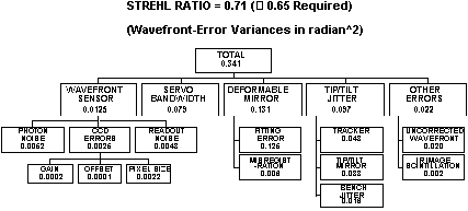
Figure 2. Clause A error budget.
Figure 2 shows the error-budget for the Clause A conditions with 8 subapertures/diameter over the WHT pupil diameter. The dominant effect is the deformable-mirror fitting error. Because the light level is high, i.e. magnitude 8 star, the wavefront sensor errors are small. The budget assumes that the wavefront sensor CCD has been calibrated to specification and the pixel size errors do not exceed 1 µm rms. A conventional centroiding algorithm was used in determining the budget for the CCD errors. The tip/tilt jitter includes an allowance of 30 nrad (0.006 arcsec) rms for jitter on the optical bench induced by telescope motion and moving bench components; this jitter is in addition to the 70-nrad (0.015 arcsec) rms tip/tilt sensor/FSM error. The “misregistration” box refers to errors associated with the incorrect mapping of the mirror actuators at the wavefront-sensor lenslet array, e.g. due to a non-zero incident angle at the deformable mirror. The optical design is such that the deformable mirror is imaged at the lenslet array. The allowance for the uncorrected wavefront error includes only those errors specified for the AO system. The contribution from the WHT optics was not known at the time of writing but this information is being sought.
The error budget in Figure 2 gives a Strehl ratio of 0.71 which is comfortably above the specified value of 0.65 for Clause A. Note, however, that several assumptions were made in deriving the error budget. In particular, the error budget may be revised when adequate turbulence data from the JOSE programme are available. Furthermore, there may be some small sources of error that have been omitted.
The ability to satisfy Clause B requires that the system operate with dim stars, e.g. visual magnitude of at least 15 or 16, and that the atmospheric conditions provide appropriately large isoplanatic angles up to about 1.5 arcminute radius. (Note that this is the field limit of the new WHT image derotator.) Data on the latter condition will be provided by the JOSE programme.
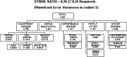
Figure 3. Clause B error budget.
The error budget shown in Figure 3 is for an on-axis visual magnitude 16 guide star; operation with a dichroic beamsplitter that allows the WFS to be used over its maximum spectral bandwidth was assumed. An integration time close to the assumed atmospheric time constant was used and, as a result of the low sample rate, the CCD noise was assumed to be 3 noise electrons/pixel. This noise level is claimed to be achievable by at least one CCD supplier. Note that in the absence of representative JOSE data, the atmospheric time constant was based on a Bufton wind profile and a modified Hufnagel-Valley turbulence profile. Figure 3 shows that several errors have increased significantly over those shown in Figure 2. An increase in sources of error such as photon noise should be expected at these low light levels. The error budget analysis for Clause B brought out the need for accurate calibration of the CCD background offset.
The model used for the error-budget analysis did not have the capability to explore any potential benefit from modal techniques and turbulent layer conjugation. These approaches will be explored using propagation codes.
4.0 Deliverable items
In addition to the tip/tilt sensor and all associated hardware, other deliverables include software and licenses, review documents, test procedures and reports, reports on analyses and simulations, user manuals, and test equipment paid for by the programme.
The delivery location is expected to be the location for system integration (TBD).
5.0 Acceptance
testing
For acceptance testing the tip/tilt sensor performance may be demonstrated under laboratory conditions using simulated guide-star images. An atmospheric coherence length, ro, of 20 cm at a wavelength of 0.55 µm shall be assumed for the purposes of a demonstration to satisfy the measurement accuracy requirement with a partially compensated image. The full width of the central peak of the simulated guide star image should subtend about 700 nrad (0.15 arcsecond) in WHT object space with a Strehl of about 0.07. A point spread function of constant shape may be used for demonstration purposes. Larger diameter images with correspondingly lower Strehl ratios should be used for demonstrating the performance in the tip/tilt only mode. The capability to function at the maximum specified sample rate (TBD) shall be demonstrated. Note that the maximum anticipated rate is 1 kHz and this value may be reduced when sufficient JOSE data are available. A pre-processor (see Section 1.6 above) will be provided by the programme for test purposes.
Other approaches to verifying the performance may be proposed subject to approval by the UK AO programme.
Reference
1. Observers' Guide, S.W. Unger, E. Brinks, R.A. Laing, K.P. Tritton, P.M. Gray, Version 2.0, November 1988, Isaac Newton Group, La Palma.