2.0 Real
Time Rack
2.1
Overview
The top-most 19" rack unit houses the real-time
control system for Naomi. Contained within this rack are:
1)
Force Sparc CPU-5 Processor which provides overall system
control and the ethernet interface to the outside world
2)
Blue Wave Systems DBV44 TI TMS320C40 Digital Signal
Processor card which receives data from the SDSU Wave Front Sensor, evaluates
centroid positions and calculates the demands to be placed on the deformable
mirror
3)
Blue Wave Systems DBV46 DSP card which passes diagnostic
information from the two DBV44s to the Sparc processor
4)
Blue Wave Systems DBV44 DSP card which controls the
deformable mirror and compensates for hysterysis by correcting actuator
position measured by strain gauges
5)
Camera interface cards (2) which receive the pixel data
from the WFS via an RS422 interface, buffer this data in a FIFO and forward the
data to the C40 comm port synchronous interface
6)
C40 DAC interface card which passes the mirror demands from
the C40s to the mirror DACs as a 16-bit wide RS422 interface
7)
Pentland 16-bit ADC cards (3) which digitise the signals
from the mirror strain gauges
8)
Timing generator card which synchronises the ADC
conversions
2.2
Force Sparc CPU-5
The Force CPU card is responsible for booting and
configuring the real-time control system for Naomi. It has a 10-Base ethernet
interface used to communicate with the outside world and, in particular, the
visualisation workstation (Navis).
The Sparc is more commonly known as aocontrol1.ing.iac.es. It has
a nine gigabyte SCSI disk which holds the operating system (Solaris 2.5) and
configuration software for the DSP system, stores real-time (flight recorder)
data and act as a VxWorks host.
The card was supplied by ACAL Electronics Ltd (Force’s UK
distributor).
A replacement card (CPU-50) is being held by the University
of Durham until such time as it and its disk have been configured. The CPU-5
card used at present is obsolete. The replacement is compatible but somewhat
faster, thus it is not possible to easily swap out the processor.
A disk crash on aocontrol1 will render the entire real-time
system inoperable so an appropriate back-up strategy must be implemented.
2.3
Blue Wave DBV44 DSP (Wave Front Sensor)
The left-most DBV44 card in the real-time rack is the
interface to the Wave Front Sensor camera. The card was supplied by Blue Wave
Systems (formerly Loughborough Sound Images). It houses eight Texas Instruments
TMS320C44 processors connected in a ring structure.
The card is constructed from a DBV44 motherboard and four
dual C40 TIMs (a small daughter card plugged onto the motherboard). A spare
motherboard and single TIM have been supplied with Naomi. It is hoped to supply
three further TIMs, to allow the spare card to be fully populated, if funds
allow.
The card is responsible for reception of the pixel data,
supplied by the wave front sensor cameras, and the calculation of centroid
positions. These centroid positions in turn are used to calculate the
reconstructed tip/tilt/piston demands to be placed on the segmented mirror to
correct the telescope image.
Pixel data is supplied by the SDSU based WFS via two RS-422
links, through two camera interface cards (see below), to comm ports attached
to two of the eight processors on the card.
2.3.1
Fault Diagnosis
The DBV44 cards have been found to be exceptionally
reliable. However, if the real-time system refuses to boot one of the
processors from its partner, it may be necessary to shutdown aocontrol1 and
power-cycle the real-time rack. Ensure the HV supply to the mirror is switched
off if this takes place.
2.4
Blue Wave DBV46 DSP (Diagnostics)
The DBV46 card is used to provide real-time diagnostics
information from the Naomi system. The card houses two TMS320C40 processors and
a large amount of local memory.
Data packets from the two DBV44 cards are received and
interpreted by the DBV46 via two comm ports. The data is processed and passed
to the Sparc processor (via VME) to be supplied to the visualisation
workstation NAVIS (via ethernet).
No spare card has been supplied as yet. It is hoped to do
so if funds allow.
No faults or problems have been encountered with the DBV46
to date.
2.5
Blue Wave DBV44 DSP (Mirror Drive)
The second DBV44 card in the real-time rack is identical to
the first in terms of its hardware. It places the demands provided by the first
DBV44 onto the segmented mirror via a further interface card.
As piezo actuators suffer from hysterysis, this DBV44
monitors the actual position of the actuator strain gauges via three ADC cards.
The demands to the mirror are modified and re-applied, at up to ten times the
WFS frame rate, to ensure the piezo actuators are sent to the correct true
position rather than one subject to hysterysis.
2.6 Camera
Interface Card
The real-time rack houses two camera interface cards. These
cards were designed and produced by the University of Durham.
The cards buffer the pixel data supplied by the WFS in a
FIFO and then pass it to the WFS C40 DSP card on demand via a comm port
interface.
One of the cards is configured as a master and one as a
slave. The master receives commands from the C40 card via a control comm port
interface and passes them to the slave as appropriate via a simple synchronous
interface on unused lines on the VME backplane.
The circuit diagram and layout for these cards are provided
in green book 77. At Durham the same card is used to interface C40 DSPs to a
WFS camera produced by RAL. A spare card has been provided which can be
configured as master or slave.
2.6.1
Circuit Description
Pixel data from the dual SDSU WFS cameras is presented to
the card as RS-422 signals on a 37 way D socket. Page 1 of the circuit diagram
shows the connections from the D connector to the four 4-way RS-422 receiver
ICs. There are 14 data bits (DATA[00:13]), an asynchronous Start Of Frame bit
(SOF) and the Strobe (STB) for synchronous data transfer.
A ‘1’ on the SOF line causes the card to become ready to
store pixel data in the FIFO. The SOF line is monitored by the Slave PLDs (U6 -
shown on page 2 of the circuit diagram). Data will only be latched into the
FIFOs (U4 and U5) if a Frame Request has been received from the C40 ring via
the Master PLD (page 3 of the circuit diagram).
The Master PLD (U26) is connected to a C40 comm port via a
26-way high-density (0.025”) pitch connector. The comm port is 8-bits wide with
Request, Acknowledge, Strobe and Ready signals. Data is always transferred as a
32-bit word sent as four successive 8-bit transfers. Data transfer on comm
ports can be bi-directional but data on this port is always originated by the
C40 and read by the Master PLD. A token forcing circuit, based around a 74ALS74
SR latch, forces the port into input-mode when interrogated by the C40.
The interface protocol from the C40 to the master PLD is
very simple. Only the first 8 bits are read by the Master PLD, the other three
8-bit transfers are ignored. The protocol allows the C40 to reset the Slave
PLDs, request a frame, place dummy data into the FIFO memory or read dummy data
out.
When the camera real-time system is running, frames are
continuously requested by the C40. The Master PLD passes the request frame
command to the two Slaves simultaneously. The Slaves will then start to put the
pixel data into their FIFOs once a SOF bit has been detected.
As data is fed into the FIFOs the state machine in the
Slave PLD simultaneously tries to output the same data to the C40 WFS ring via
two comm ports. These comm port connections take place on the VME interface and
not on 26-way cables. A token forcing circuit is included on these ports to set
them to output-mode when interrogated by the C40. A small daughter card has
been fitted to the VME backplane to allow these connections to be made.
Provided the two receiving C40s are ready to accept data,
the FIFOs should never fill up. The FIFOs are large enough to hold a complete
frame of binned data if required.
The Slave PLD will only stop receiving data and passing it
to the C40s if a new frame is detected without a frame request having been
received from the Master PLD.
2.6.2 Card
Replacement
The spare card is currently configured as a Master. To
configure the card as a slave it is necessary to remove U26 (master PLD) and
U11 (a 74LS245 which drives the master-to-slave signals).
2.7 C40
DAC Interface Card
This card was designed and produced by the University of
Durham. It accepts the mirror demands from the mirror C40 card via a comm port
and passes this data to the DAC interface card as 16-bit wide RS-422.
The circuit diagram and layout for these cards are provided
in green book 63. A spare card has been provided.
2.7.1 Circuit
Description
The card has two comm port connections. One port acts as a
data port and the other as a sync port. A token forcing circuit on the sync
port sets the port to input only. The data port on the C40 is set to
output-mode by default.
The majority of the circuit handles the reception of the
comm port 32-bit data transfer as two 8-bit byte pairs. These byte pairs are
stored in two small FIFOs.
The FIFOs temporarily store the byte pairs until the second
byte has been received. Once the second byte has been placed in the FIFO,
indicated by the higher FIFO empty line going high, both bytes are read out,
converted to RS-422 and output simultaneously via a 40-way IDC cable to the DAC
interface card.
A single write to the sync comm port by the C40 causes the
FIFOs to be flushed and a reset signal to be sent to the DAC interface.
The protocol used to transfer DAC data is very simple. A
write to the sync port resets the DAC interface address counter to zero. 128
writes to the data comm port then take place. Each write sends two words of
16-bit data to the DAC interface which is in turn output to the DAC cards along
with an incrementing address.
2.8
Pentland 96 Channel ADC Card
There are two Pentland 96 channel, 16-bit ADC cards within
the real-time rack. These are used to digitise the strain gauge feedback
signals and pass the results to the mirror control C40 ring. These cards were
chosen as they have a C40 comm port interface as standard.
Together with the 64 channel card, these cards provide 256
ADC channels. Only 228 are used for strain gauge signals, with a further two
being used for temperature monitoring.
These cards were purchased direct from Pentland UK.
2.9 Pentland
64 Channel ADC Card
The 64 channel ADC card supplements the two 96 channel
cards to provide 256 ADC channels in total.
2.10 Timing
Card
This is a simple card which produces timing pulses to
synchronise the conversions by the three ADC cards. A BNC connector is provided
to allow the timing pulses to be monitored if required.
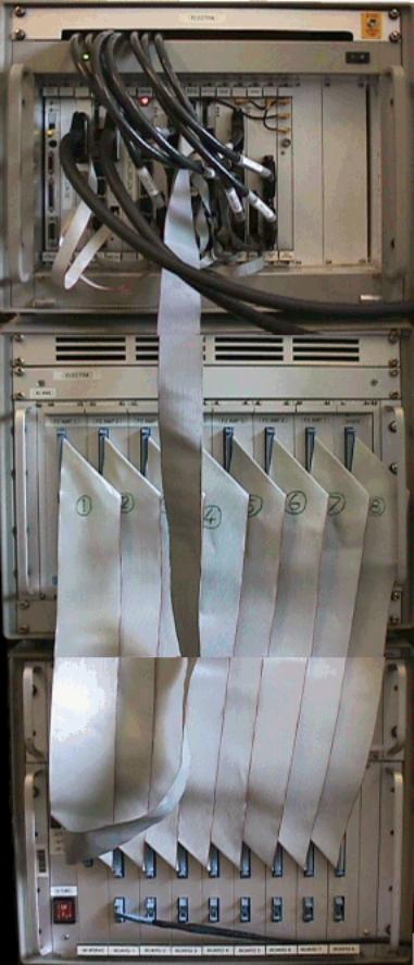
3.0 High
Voltage Amplifier Rack
The high voltage amplifier rack houses the eight 30-channel
high voltage amplifier cards and an interlocked fan tray to keep the amplifiers
cool.
3.1
Overview
The power supply for the high voltage amplifiers is
actually housed in the DAC rack due to lack of space. The mains supply to the
high voltage power supply is routed through the fan tray such that it is
impossible to power the amplifiers if the fans are not running. This mains
supply is further routed such that the high voltage cannot be turned on unless
the DACs themselves are powered (to ensure that random demands are not placed
on the mirror).
3.2 Electrical
Connections
|
|
|
|
|
 |
|
|
|
|
Figure 4 – Electrical Connections
|
|
The DACs and high voltage amplifiers must be powered down
before disconnecting the segmented mirror. See section 9 for further details.
3.3 30
Channel Amplifier Card
The circuit diagram and layout for the high voltage
amplifier card is shown in green book 71.
The circuit is based around an inverting, differential
input, amplifier circuit with a forward gain of 20. The circuit accepts +/- 10V
input signals and amplifies them to +/- 200V using Apex PA15 amplifiers.
A spare card has been provided along with several spare
amplifier chips.
Each amplifier unit has two pairs of 1N914 diodes across
the input to limit the common mode voltage to a safe level. Two diodes on the
output provide over-shoot and under-shoot protection. A 1K resistor on the
output limits the output current to a safe level. A pair of resistors divide the
high voltage output to a safe level and pass it to a 37 way D test connector. A
separate meter unit has been provided which allows the output of an individual
channel to be checked via the test connector.
3.3.1
Amplifier Replacement
The PA15 amplifiers have been found to be very reliable
(unlike their predecessor the PA87). In the unlikely event that an amplifier is
thought to have failed then follow the following procedure:
Connect the meter test unit to the card in question and
select the appropriate output channel. Use MirrorMimic to change the output
voltage and check that the amplifier swings between +/- 100% stroke.
Be sure to select the correct output!
Mirror columns 1 and 2 are driven by amplifier card 1
(using all 30 channels). Mirror columns 9 and 10 are driven by amplifier card 8
(likewise). Mirror column 3 is driven by amplifier card 2 but only using
channels 1 to 24 (channels 25 to 30 are unused). Mirror column 4 is driven by
amplifier card 3… etc …
If an amplifier has failed then replace as follows:
1) Observe
anti-static precautions!
2) Power
down the high voltage system and replace the faulty card with the spare as
appropriate
3) Unscrew
and remove the top (metal) and bottom (resin) covers
4) Identify
the blown amplifier (with the circuit board the normal way up, the heatsinks on
top, the front panel to the left and the backplane connectors to the right:
amplifier 1 is in the top right corner; amplifier 6 is in the top left corner;
amplifier 7 is below amplifier 1; amplifier 25 is in the bottom right corner;
amplifier 30 is in the bottom left corner)
5) Using
a shortened allen key - undo the retaining bolt on the amplifier
6) Prise
the amplifier off the heatsink using a knife
7) Hold
the amplifier with pliers or forceps
8) Turn
the board over and heat all ten legs on the amplifier simultaneously (best
achieved using a 1” wide bit and plenty of solder)
9) Pull
the amplifier from the board once the solder melts on all legs
10)Clean
the holes with a solder-sucker
11)Apply
fresh heatsink compound to the new amplifier
12)Place
it through the board and secure with the retaining bolt
13)Solder
the legs
14)Test
the board using the test slot in the high voltage rack positioned between cards
1 and 2 (remove both cards and locate the repaired card on the extra set of
connectors – connected only to capacitive loads and not the mirror)
15)Connect
DAC cable one to the card
16)Use
MirrorMimic and the test meter unit to check the repaired board (using the
outputs for segments 1 to 10)
17)Replace
the covers and put the board back into service
4.0 DAC
Rack
The bottom 19" rack unit houses: the digital to
analogue converters which feed the high voltage amplifiers for the segmented
mirror; the +/- 220V DC power supply for the high voltage amplifiers; the power
supply for the strain gauge amplifiers and the power supply for the ‘sin-bin’
amplifier.
4.1
Overview
Within the DAC rack are four sub-assemblies plus a mains
distribution panel.
On the front of the rack are:
1)
Sub-rack assembly containing two 220VDC power supply
modules
2)
Sub-rack containing the DAC cards (8), DAC interface card
and the mains power switches for the DACs and HV amplifiers
On the rear of the rack are:
3)
Sub-rack containing the power supply for the strain-gauge
amplifiers
4)
Sub-rack containing the power supply for the ‘sin-bin’
amplifier
5)
Mains distribution panel
4.2
Electrical Connections
The electrical connections for the DAC rack are shown in
section 3.2 as they are inter-connected with the high voltage rack.
The strain-gauge amplifier power supply and ‘sin-bin’
amplifier power supply are each powered via a standard IEC mains plug but have
been joined to a common 13A mains plug so that their power can be provided from
a single filtered supply if required.
The ‘sin-bin’ amplifier power supply has an illuminated
mains power switch adjacent to the mains inlet. The strain-gauge amplifier
power supply has a non-illuminated mains switch above the mains inlet.
The strain-gauge amplifier power supply and ‘sin-bin’
amplifier power supply must both be powered down before disconnecting the
segmented mirror. See section 9 for further details.
A 3 pin Din cable carries the +/- 12V DC output from the
strain-gauge amplifier power supply to the ‘sin-bin’ power supply. These rails
are used to power part of the ‘sin-bin’ amplifier but also act as an interlock.
The +/- 12V powers two relays within the ‘sin-bin’ power supply such that the
power is turned completely off if
either 12V rail fails. This is to prevent possible damage to the ‘sin-bin’
amplifier caused by the amplifier inputs being powered without a supply rail
present.
4.3
DAC Interface Card
This card was designed and produced by the University of
Durham. The circuit diagram and layout for the card are contained in green book
62. A spare card has been provided.
The DAC interface card accepts successive RS-422 16-bit
data writes from the C40-DAC interface card and outputs these values together
with an incrementing 16-bit address onto a standard 3U VME backplane.
4.3.1
Circuit Description
The C40-DAC interface card outputs a reset signal followed
by 256 16-bit data writes via an RS-422 parallel interface. The DAC interface
card receives these data writes and outputs the values together with an
incrementing 16-bit address onto a VME backplane.
The 16-bit address is generated by two 74ALS579 counter
ICs. Their value is reset via the active low reset line from the C40 interface.
Successive writes cause the address value to be incremented.
The 16 data lines are converted to TTL by a set of HCPL2602
opto-isolated RS-422 receivers. This data is then buffered by two 74ALS541 ICs.
These ICs are permanently enabled and do not latch the data in any way. The data is then simply presented on the
backplane.
The write signal from the parallel interface is converted
to TTL by another HCPL2602 receiver and is then passed to the backplane and
used to increment the address counters. The falling edge of the write signal is
used by the DAC cards to latch the data. The rising edge causes the address
counter to be incremented after a 30nsec delay.
4.4
32 Channel DAC Card
This card was designed and produced by the University of
Durham. The circuit diagram and layout for the card are contained in green book
61. A spare card has been provided.
The DAC rack contains eight identical DAC cards. Each card
provides 32 channels of 13-bit, +/- 10V output from four Maxim MAX547 DAC ICs.
A bank of DIP switches selects the base address for each card:
Card DIP Switch Setting
1 2
3 4 5 6 7 8
1 (Channels 0-31) C C
C C C C C C
2 O C
C C C C C C
3 C O
C C C C C C
4 O O
C C C C C C
5 C C
O C C C C C
6 O C
O C C C C C
7 C O
O C C C C C
8 (Channels 224 – 255) O O
O C C C C C
(C = Closed, O = Open)
The two channels used to drive the tip-tilt or fast
steering mirror are 30 and 31 and are output by DAC card 1. Hence the tip-tilt
interface cable should only ever be connected to DAC card 1.
The 60 way IDC connector provides 30 DAC output + ground
pairs. The 10 way IDC connector provides the remaining two DAC output + ground
pairs.
4.4.1
Circuit Description
The DAC card houses four 8-channel 13-bit DAC ICs (Maxim
MAX547). The ICs are memory mapped on the card using 13 address lines (in
practice only 8 lines are actually used):
A0 – A2 select the DAC channel on a particular DAC chip.
These three lines are connected to the A0 – A2 inputs on all four DAC chips.
A3 & A4 are decoded to provide the chip enable (active
low) to one of the four DAC chips. A3 and A4 are interfaced to a 74ALS138
de-multiplexer IC which decodes their state into one of four outputs. The
active low enable of the de-multiplexer is connected to the address write
signal providing the chip select signal to the correct DAC.
A5 – A7 provide the base memory address for the DAC card
These address lines (together with A8 – A12) are passed to an 8-input-pair
comparator IC (74ALS520) which decodes the card base address. The output from
the comparator is connected to a second active low enable on the de-multiplexer
IC ensuring that the write signal only becomes a successful chip enable if the
address matches one of the 32 values for that DAC card.
In theory, 256 DAC cards (providing 8192 DAC channels)
could be connected to the same system if required, although the backplane drive
electronics would need to be enhanced to drive that many loads and length of
backplane.
The 13 data lines are connected to all four DAC chips. The
data lines are read by the DAC chip when the appropriate chip enable is
decoded.
A MAX 873 provides the 2.5V reference voltage for the DAC
chips.
The +/- 2.5 V output from the DAC chips are buffered and
amplified by a set of LM348 op-amp ICs. The gain of each amplifier is –4
providing an inverted +/- 10V output from the card to the high voltage
amplifiers.
The address, data
and write signals are provided by a standard 3U VME type backplane and
are generated by the DAC interface card. See previous section.
4.5
Strain Gauge Amplifier Power Supply
The power supply for the strain gauge amplifier is housed
in a 19” sub-rack on the rear of the DAC rack. It contains a +/- 12V, +3V DC
power supply. The 3V rail is generated from the +12V rail using a 2.5V
reference and a power op-amp circuit.
The circuit diagram and layout for the power supply are
loose within the Electra documentation collection in the GHRIL NAOMI cupboard.
The three voltage rails are passed to the strain gauge
amplifier rack via a 4-way cable with locking Amphenol-type connectors. The +/-
12V rails are also passed to the sin-bin power supply.
4.6
Sin-Bin Amplifier Power Supply
The power supply for the sin-bin amplifier is housed in a
19” sub-rack on the rear of the DAC rack. It contains a 10 channel +5V, +3V DC
power supply. Each 5V/3V rail pair are completely isolated from the others by
means of a separate transformer winding per pair, to allow the sin-bin
amplifier to operate correctly.
The +/- 12V rails from the strain gauge amplifier power
supply are also passed to the sin-bin amplifier and are used as a power
interlock. A pair of relays remove power to the sin-bin power supply if either
12V rail fails.
The voltage rails are supplied to the sin-bin amplifier via
a 37 way D cable containing 10 sets of 5V/3V/0V connections plus the +12V/-12V/0V connections from the
strain gauge amplifier power supply.
5.0
Deformable Mirror
This section describes the deformable mirror itself and its
associated amplifiers.
5.1 Overview
The deformable mirror assembly contains:
1)
ThermoTrex 76 segment mirror with strain gauge feedback
2)
Strain gauge amplifier sub-rack
3)
Sin-Bin amplifier
4)
X & Y motion stages
The segmented mirror was made by ThermoTrex Corporation
(San Diego) in 1995. It is one of a kind. There are no spare actuators and even
if spares were available it would be impossible to replace an actuator without
compromising the flatness of the mirror (+/- 1 µm). A ‘spare’ continuous phase
sheet mirror (Xinetics 97 actuator) is held by Durham and could be used to
replace the ThermoTrex mirror should it fail or be damaged. However this
replacement would not be a simple process due to the nature of the software
required to drive the two mirror types and would almost certainly involve
several weeks of down time.
The mirror has 76 segments, each of which is moved by a
piezo actuator tube. Each piezo actuator has three electrodes (separated by 120
degrees) which can move the mirror in tip, tilt and piston, giving the mirror
228 degrees of freedom. Each actuator also has three pairs of miniature strain
gauges fitted to measure the actual position of the mirror allowing the effects
of piezo hysterysis to be overcome. The signals from the strain gauges are
amplified before being relayed to the ADCs within the real-time rack.
The mirror is flat to within 2µm in its relaxed state. The
actuators have a stroke of 6µm leaving 4µm of useable stroke after the mirror
has been flattened.
The mirror can be displaced in X and Y using two stages
provided by ATC. This displacement is required for alignment but also to allow
the white-light flattening technique to be used (where the mirror is sheared
with respect to its lenslets in the X direction) and to correct pupil
registration for off-axis guide stars.
5.2 Electrical
Connections
This section describes the connections to the mirror
assembly.
5.2.1
High Voltage Connections
Each actuator tube has three drive signal connections and
one common return. The three electrodes on the outside of the actuator tube are
connected via three wires: white, red/white and green/white. The common (earth)
electrode covers the entire inner surface of the tube and is connected via a
violet wire.
The high voltage signals are passed from the high voltage
amplifier rack to the mirror via two custom cables with ITT Canon 144 way ZIF
connectors. The cables are bulky due to their 450V rating. A wiring diagram for
the cables and connectors is included in the green ‘Electra Wiring’ folder in
the Naomi documentation.
5.2.2
Strain Gauge Signal Connections
Each piezo actuator contains three pairs of miniature
strain gauges to measure the mirror position. For each pair of strain gauges,
one gauge is active whilst the other provides temperature compensation.
The active strain gauges are adhered to the inside of the
actuator. The temperature compensating gauges are adhered to a small ceramic
circuit board which also provides connection points to the five core screened
signal cable.
Figure 5 shows the connections to the strain gauges. Each
gauge has a nominal impedance of 500 ohms. The gauges were made by Entran (ESU
series).
5.2.3
Strain Gauge Impedance-to-Earth Fault
When ThermoTrex adhered the measuring strain gauges to the
inside of the piezo actuator tubes, they intended to scrape away the earth
electrode contact from below the gauge sites to ensure the gauges are
electrically isolated. Unfortunately this appears to have failed for nine of
the actuators.
The strain gauges are so small that the resistive material
runs right up to the edge of the gauge body. We believe that for the nine
faulty actuators the earth contact was not correctly removed and so creates a
path-to-earth part way up the measuring strain gauge. This effectively acts as
a short between these actuators in the amplifier circuit.
To try and work around this impedance to earth fault we
introduced the sin-bin strain gauge amplifier which provides an isolated power
source and amplifier for each faulty actuator and which can tolerate one path
to earth.
The sin-bin amplifier restores the faulty actuators to
normal use but does leave then more prone to electrical noise than the normal
actuators. This is partly due to a lack of proper screening around the sin-bin
amplifier (due to space constraints) but is mainly due to the impedance fault
acting as an antenna into the gauge amplifier circuit.
5.3
Strain Gauge Amplifier
This section describes the amplifier used to boost the
output of the actuator strain gauges.
5.3.1
Overview
The strain gauges within the piezo actuators are driven
from a 2V precision source. This is to ensure the gauges are not damaged due to
excess power dissipation, but also to ensure that the mirror remains as cool as
possible under normal use. The gauges have a maximum power rating of 50mW.
Powered in pairs from 2V, they dissipate 2mW each.
The gauge factor of the gauges is 140. So for a +/- 3um
full range displacement over the actuator length of 27mm this corresponds to a
change in resistance of 7.8Ω. Hence the nominal output of each strain
gauge pair is 1V +/- 7.7mV
To boost this signal to a level which will survive the 5m
cable run to the ADCs, and to be at a useable level for digitisation, a rack of
Burr-Brown INA118 precision amplifiers is used.
The gain of the amplifier circuit has been carefully chosen
to allow a simple precision resistor divider pair to act as the voltage
reference. The gain ensures that the resistor and gauge tolerances keep the
amplified signal within the +/- 10V range of the ADCs and that no manual offset
components or adjustment are required.
Each amplifier card carries 32 amplifiers and so buffers
the outputs from one entire column of segments. The amplifier rack mounted
above the mirror itself and carries ten identical cards. The output signals
from these ten cards are combined onto eight SCSI-type cables for connection to
the Pentland ADCs.
5.3.2
Connections
The strain gauge signals are passed to the amplifier cards
via reverse DIN41612 style daughter boards. These boards were produced by
ThermoTrex. A small ‘backplane’ is included to allow the +/- 12V, +3V power to
be passed to all 10 amplifier cards.
The amplified signals are output on 68 way SCSI connectors.
These are combined with the sin-bin amplifier outputs and passed to eight
further SCSI connectors to be passed to the ADC cards.
5.4
Sin-Bin Amplifier
This section describes the sin-bin amplifier card. This
card was designed and produced by the University of Durham and it and its power
supply are documented in green book 8?.
5.4.1
Overview
The sin-bin amplifier is a copy of the standard strain
gauge amplifier but each triple channel of amplifiers has an isolated reference
supply. The sin-bin power supply provides 10 channels of 5V & 3V power. The
5V is regulated to 2.5V by a MAX873 reference. This is regulated to 2V by an
AD8532 amplifier running from the 3V rail. This circuit was adopted to ensure
the minimum of power dissipation within the mirror enclosure.
The three INA118 amplifiers for each of the 10 triple
channels are powered from the same +/- 12V rail as the normal strain gauge
amplifiers. The high common mode rejection ratio of the amplifiers is
sufficient to overcome the impedance-to-earth fault allowing the circuit to
effectively tolerate being pulled to earth part way up the measuring strain
gauge.
5.4.2
Connections
Power is provided to the sin-bin amplifier via a 37 way D
cable.
The screened connections to the strain gauges themselves
are fed in via 7 pin Fisher type connectors.
Each channel output its signals via a 10 way IDC connector.
The cables from these connectors are carefully wired into the ADC signal cables
at the correct point. These connections need to be removed if the top is to be
removed from the mirror assembly (eg. for access to the sin-bin amplifier
itself). The connectors are all numbered.
6.0
Interconnect
This section describes the various cables used within the
real time system.
6.1 Real-Time
Rack
The real time rack contains the following ‘internal’
connections:
Several C40 comm port connections:
These
connections are all made using 0.025” pitch ribbon cable and 26way high density
connectors. The cables are all pin-for-pin however one of the pins is blocked
by a polarising plug depending on whether it is connected to a default input or
output comm port.
ADC timing signals
These
connections are made via three short 50 SMC cables. The order of the
connections is not critical as all three signals are synchronised.
The eight SCSI type
strain gauge cables connect to the three Pentland ADC cards (labelled 1 to 8).
These cables are 68-way SCSI type, pin-for-pin with plugs at both ends. They
were produced by Black Box.
The two RS-422 cables carying the
SDSU WFS data are connected to the camera interface cards (labelled Master and
Slave). These cables are terminated in 37-way D plugs and contain 18 twisted
pairs allowing up to 16 data lines plus start-of-frame and strobe lines to be
carried. In practice the higher two data lines are the start-of-frame and
strobe in the Naomi 14-bit configuration and the start-of-frame and strobe are
unused.
The cable from the C40-DAC interface
card to the DAC interface card is 40 way 0.05” IDC pin-for-pin. It carries the
16 RS-422 data line pairs plus reset and write connections.
The rear of the rack reveals the
ethernet connection and the mains inlet. A 25way D connector is provided to
connect a VT terminal to aocontrol1 if required.
6.2
High Voltage Amplifier Rack
This rack does not have any ‘internal
‘ connections, only connections between this and the other racks and the
mirror.
On the front of the rack are the 8
DAC output cables which are all 60 way 0.05” IDC cables connected pin-for-pin.
The rear of the rack reveals the two
high voltage cables with their 144 ZIF connectors. The +/- 220V supply via a
white mains cable and Amphenol type connector. The mains supply to and from the
fan tray (interlocked with the DAC power and the HV amp power).
6.3
DAC Rack
On the front of the rack are the 8 DAC output cables (see
above) and the C40-DAC interface cable (see above).
The tip-tilt drive signals are connected to DAC card 1 on
its 10 way IDC connector. Pin 2 is the X signal with Pin 1 as its ground. Pin 4
is the Y signal with Pin 3 as its ground.
The tip-tilt interface cable depends on which mirror is
connected. For the Durham tip-tilt mirror this cable is terminated in two SMB
sockets to be connected to the tip-tilt drive rack.
If the Zeiss mirror is re-introduced into the Naomi system
then the cable will need to be extended to allow the back of the filter rack to
be reached. Both the extension cable and the 9-way D signal cable (from the
filter rack to the Zeiss rack) have been provided.
6.4
Fast Steering Mirror Cable
This cable is described in the previous section.
6.5
SDSU – RS422 Driver Card
This card was produced by the University of Durham and is
documented in a loose sheaf of A4 printout in the Naomi documentation
collection.
The card simply isolates and buffers the TTL signals output
by the SDSU VME cards to RS422. A 5V DC-DC converter provides power supply
isolation between the VME rack and the RS-422 driver ICs. HP opto-isolators
isolate the 14 data lines plus start-of-frame and strobe signals.
Naomi only uses 14 data bits to transfer data but this card
was made such that it can support all 16 data lines from the SDSU system if
required. A header can be replaced to allow all 16 data lines to be used.
6.6
SDSU – RS422 Cable
This cable is the twisted pair 37 way D cable documented in
the real-time rack section above.
6.7
High Voltage Drive Cables
These are the two custom made 450V 144 way ZIF cables
documented in section 5.2.1.
6.8
Strain Gauge Signal Cables
These are the eight SCSI-type cables documented in the
real-time rack section above.
6.9
Strain Gauge Amplifier Power Cable
This is a four core grey cable terminated in Amphenol type
connectors.
6.10
‘Sin-Bin’ Amplifier Power Cable
This is the 37 way D cable documented in section 4.6.
6.11
C40 – DAC Interface Cable
This is the 40-way IDC cable documented in the real-time
rack section above.
6.12
Earth Cables
The NAOMI system MUST be earthed!
An earth star point is present on the rear of the DAC rack.
All three racks must be connected to this point.
Additionally, an earth cable from this point to the optical
bench must be connected.
The two high voltage cables to the mirror are also earthed.
One end is connected to the star point and the other to the optical bench near
the mirror high voltage connections.
7.0 Cooling
Circuit
The following NAOMI units require water cooling from the Neslab
chiller:
1)
The two WFS SDSU controllers
2)
INGRiD SDSU controller
3)
Calibration unit discharge lamp (although this may be
replaced with a non-cooled lamp in the future)
4)
The WFS CCD peltier coolers
Care should be taken when connecting the cooler supply to the
WFS SDSU controllers as the flow and return connections have the same conector
type. Ie. It would be possible to connect two flow connections to one
controller and two return connections to the other resulting in two very hot
controllers. These connectors should be carefully labelled or their connectors
should be changed so this is not possible.
These circuits should be connected into the Ghril cooling
circuit if possible.
8.0 FISBA
Interferometer
This section describes the FISBA interferometer
8.1 Overview
The uPhase interferometer was supplied by Armstrong Optical
(the UK distributor for FISBA products).
The interferometer comprises:
1)
PC (fisba.ing.iac.es) running Windows 98 (Second Edition)
2)
ISA interface card installed in above PC
3)
Interferometer module mounted on the rear of the 100mm
collimated lens or the f/9 or f/5 lenses
4)
Stabilised HeNe laser with mono-mode fibre output
The interferometer software set comprises:
1)
FISBA uShape software: software package supplied with the
interferometer to allow surface measurements to be made
2)
UShapeFTP: software written by the author to transfer the
raw interferometer images to the visualisation workstation (navis) via FTP
The interferometer can either be used to view the
deformable mirror (using a single or double pass configuration) or used as a
measuring instrument through the whole of Naomi.
If you are using the interferometer to align (or measure
the alignment of) Naomi then simply follow the procedures in the uPhase manual.
Tully Peacocke at ATC has a good working knowledge of the interferometer so it
is suggested that he be contacted with regard to using the system in this way.
Using the interferometer (with 100mm collimated lens) to
view and flatten the deformable mirror requires the use of a software package
called uShapeFTP. This package was written under Visual Basic and is stored on
fisba.ing.iac.es in the directory c:\Program Files\uShapeFTP. A full
installation of Visual Basic has been made on the PC and can be used to modify
the software if required.
8.2
Connections
The HeNe laser draws its power from an isolated ‘wall wart’
power supply. It is recommended that the laser be earthed to prevent high
voltages from being accumulated on the laser body. An earth connection is
provided on the rear of the laser.
The laser beam is supplied to the interferometer via a
mono-mode fibre. The fibre ends are VERY soft so great care should be taken
when handling the fibre. Install the fibre with the green pen marks uppermost
as the rotation of the fibre is critical to its alignment.
The interferometer connects to the PC ISA card via a 9 way
D cable. The pin-out of this cable is not known but the cable has been
successfully extended by 2 metres (using a 9-way screened pin-for-pin male to
female cable) to allow the PC to be installed in the GHRIL electronics room.
The PC has standard mains, monitor, keyboard, mouse and
network connections. The PC has an ATI All-In-Wonder video card installed which
allows the display to be routed to a VGA monitor and composite video monitor
simultaneously. A 5m extension cable has been provided to allow the VGA
monitor, keyboard and mouse to be used in the GHRIL optics room. The composite
video link plugs into a Phono connector on the black AV Out cable from the
video card. It is possible to route this to two monitors simultaneously (eg.
small monitor on the optical bench and large monitor in WHT control room).
8.3
uShapeFTP Software
The uShapeFTP package was written by the author using
Visual Basic. The software source is in a directory called C:\Program
Files\uShapeFTP.
The software should start automatically when the PC is
turned on.
The software spawns the FISBA uShape software and logs in
as ‘Supervisor’ with the password ‘u’. The software then forces uShape to
display a raw intensity image from the interferometer. The software uses the
AppActivate and SendKeys commands to control the uShape software.
The software then opens an FTP connection to
navis.ing.iac.es and checks for the existence of a file called interfero.dat in
the directory /software/Electra/save. If this file exists then the software
sleeps for 0.5 seconds before checking for the file again. Once the file is
deleted (by the Four Bucket software on navis) then the software forces the
uShape program to take a raw intensity view of the interferometer and save it
to disk. The software then opens this file, extracts the data (the file format
is specified at the back of the interferometer manual), saves this to a file in
the TEMP directory and then FTPs it across to navis. Navis then sees the file
being created and uses the data in the mirror flattening technique.
At some stage this software should be re-written under
Linux (provided the interface card details can be extracted from FISBA) to
allow simpler, faster operation. This would also allow a common PC to be used
to control the interferometer and the SBIG camera for remote optical imaging.
The fisba PC has not been backed-up (although the uShapeFTP
software is stored at Durham and will be sent on CD with the PCB design files)
so this should be done as soon as possible.
9.0
Stand-Down Procedure
The following procedure should be adopted when standing
down the Naomi system:
1)
Perform a normal Windows shutdown on the fisba PC (it will
turn itself off automatically when the shutdown completes). Turn off its
monitor. Remove the monitor, keyboard and mouse as appropriate. Disconnect the
interferometer (this can be done at the PC or at the end of the 9-way extension
cable if required). Turn off and disconnect the interferometer laser power
supply. Disconnect the laser fibre. Remove the laser and fibre from the
overhead rack and store in their original packaging. Place some tape over the
fibre entry on the rear of the interferometer. If removing the interferometer
from the 100mm lens then ensure both red dust caps are fitted. The dust caps
are normally screwed together and stored in a small polished wooden box
labelled FISBA Tools in the GHRIL cupboard.
2)
Ensure the Naomi control software has been commanded to
open the strain-gauge loop and mid-range the deformable mirror. Ensure the
software for the tip-tilt mirror has been set to its zero position. Switch off
the high voltage supply to the deformable mirror (red illuminated power switch
on DAC rack). Switch off the DAC power (second red illuminated switch on DAC
rack). Switch off the tip-tilt drive rack (top of the ATC electronics rack).
Open the inspection panel in the GHRIL wall behind the Naomi electronics rack
from the GHRIL optics room. Reach in a switch off the sin-bin power supply (red
illuminated switch on rear of DAC rack). Switch off the strain gauge amplifier
power supply (black non-illuminated switch next to mains IEC inlet).
3)
If required, log in to aocontrol1 remotely and perform a
Unix shutdown. The power can then be turned off on the front of the real-time
rack. This should not normally be necessary and remote access to aocontrol1 is
desirable even if Naomi is stood down.
4)
Power down all the components in the ATC electronics rack:
Peltier coolers; naomisdsu controller (VME crate); naomiomc controller (VME
crate); twin SDSU power supplies (two grey boxes at the bottom of the rack);
twin mechanisms power supplies (two green illuminated switches); epics
interface rack (red illuminated switch on rear of rack containing two Vero
switch mode power supply units); NCU calibration lamp. Power down the entire
rack using the switch at the rear bottom right hand corner of the rack on a
vertical mains distribution panel.
5)
Switch off the Neslab chiller after allowing the Peltier
coolers to reach ambient temperature (few minutes).
6)
Disconnect the cooling pipes to the SDSU controllers etc.
Store the pipes under the optical bench. Disconnect the dry air supply to the
WFS.
7)
Disconnect all the cables to the WFS.
8)
Disconnect the cables and fibres to the two SDSU
controllers.
9)
Disconnect the tip-tilt mirror.
10)Disconnect
all the cables to the Naysmith Calibration Unit.
11)Disconnect
the high voltage, strain gauge, power and mechanism cables to the deformable
mirror, Disconnect the high voltage cable earth. Install shorting plugs on the
high voltage connectors on the mirror housing (not supplied at present – should
be supplied shortly). Install shorting plugs on the 8 strain gauge cables
(likewise). Install shorting plug on the sin-bin power connector (likewise).
Leave the bench earth cable connected until the last moment.
12)Carefully
drape all the cables over the two black hooks on the GHRIL wall.
13)If
possible leave the bar crossing the over the de-rotator in place as this will
retain the high voltage and earth cables. Remove the cable rack.
10.0 Installation
Sequence
To re-install Naomi the following procedure should be
adopted:
1)
Install the optical bench. Replace any components removed
for storage.
2)
Connect the bench earth cable to a point close to where the
deformable mirror will be installed.
3)
The high voltage and earth cables should be run through the
lower cable port next to the de-rotator, supported by their own crossbar and
kept physically separate from the strain gauge cables.
4)
Install the cable rack.
5)
Drape the cables over the rack and connect to the equipment
on the bench.
6)
Connect the dry air supply to the WFS. Set to 1 bar and 0.5
to 1 litre/min flow rate.
7)
Connect the cooling pipes to the SDSU controllers etc.
8)
Power up the strain gauge and sin-bin power supplies behind
the GHRIL wall panel.
9)
Power up the real-time rack (if it was turned off).
10)Power up
the Neslab chiller
11)Power up
all the ATC rack items.
12)Power up
the DACs.
13)Power up
the high voltage supply only when it is necessary to run the deformable mirror.