 2
Overview and context
 2
Overview and context
2
Overview and contextSection 3 defines the system more formally. UltraDAS' architecture was chosen to match an existing standard, described in document OBS-ARCH-1, and the interesting specialities of the implementation are discussed in the technical overview, in section 6, and in various external background papers. Hence, section 3 is really a set of general-arrangement diagrams with pointers to the documents that define the formal interfaces between components.
Section 4 lists design data for the major components; in the main, these are compiled programmes.
Section 5 states some of the perceived risks to the project.
Section 6 discusses some of the important design choices.

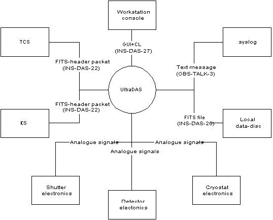
Figure 2.1: system boundary for UltraDAS.
Controls for observers and engineers are shown separately because there is a special graphical interface for technical staff. The consoles are X11 displays on workstations or X terminals. Typically, the observer's console is the console of the system computer and the TO's console, if present, is an X terminal. The console of the DAS computer may not be available as part of the observing system because the DAS computer itself is not necessarily in the control room.
There can be multiple instances of each GUI.
The data discs are on the system boundary. These discs are provided as part of UltraDAS but are also shared with the ING data-manager which is definitely outside UltraDAS. The discs are also shared with the data-reduction computer and are, in fact, generally available via NFS.
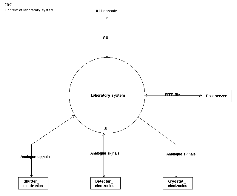
The main diagram applies to UltraDAS as deployed on the telescope. Separate provisions are made for working with cameras in the laboratory and the context diagram (Figure 2.2) for this is simpler. There is exactly one console with one GUI. There is no system log. The discs may be local or served over the LAN. There is no interaction with TCS and ICS. The analogue connections to the camera are the same as the main system.

Figure 2.2: boundaries of the laboratory system.
The UltraDAS is a part of the general observing-system. As such, it uses the client-server architecture described in document OBS-ARCH-1. This choice means that an observer can treat the UltraDAS, the TCS and the ICS as one merged system, controlling them from one point and using common scripting-languages. UltraDAS provides a vertical slice of the observing systems; the project delivers programmes for the UI, client, server and embedded layers.
The network diagram shows the computers and peripherals within and surrounding UltraDAS.
The client side of UltraDAS runs on the system-coordination computer of the observing system. The user commands are built as transient-client programmes in the usual style and there are also various GUIs. The transient clients define the sequential operations of the system and the GUIs are simple event-driven programmes that display state data from the servers and fire off transient clients to execute the commands.
The server part of UltraDAS is an UltraSPARC computer (as the system's name indicates). This machine - the "DAS computer" - is dedicated to camera control and data acquisition. It runs Solaris and is connected to the system computer by DRAMA communications.
The embedded layer is the detector controllers. These are described in the maker's manual. The system treats them as intelligent peripherals of the DAS computer. The hardware units in the controllers are standard products of SDSU and their partner companies, but the programmes running in the controllers are produced by and for ING.