 3
System design
 3
System design
3
System designThe commodity hardware is described quite briefly with a single network-diagram and some notes. There is relatively little detail to specify for this equipment.
The software is described using UML. Decomposition to individual classes is not persued in this document. The lowest level of decomposition is executable components, and the UML pictures are deployment diagrams.
Much more detail is given for the software than for the hardware because
the software is specially designed for UltraDAS.
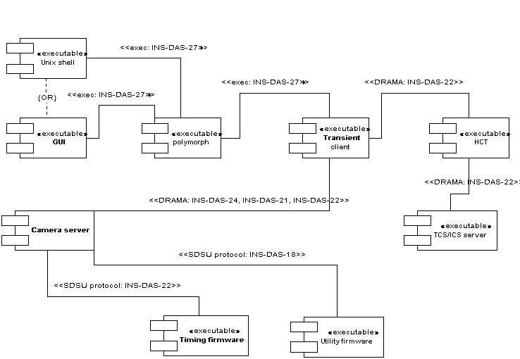
In this picture, one can see the chain of command from the UI down to the embedded programmes for one transaction. The stereotypes on the links in the diagram list the documents defining the interfaces.
The shell and GUI are alternative user interfaces: both can be active in the system at once, but any one transaction on the system is invoked from a single UI. The UIs start a command by executing a copy of the polymorph programme in a sub-process. Because the link to the polymorph component is by execution of a separate programme for each command, the GUI programmes can be made in any technology and language that knows how to run an external programme; there is no need to use a DRAMA-enabled component at this level.
Polymorph is a command reformatter. It exists to expand the command
issued by the user into a more definite command to a transient-client programme.
For example, the user-command run 10 might get expanded into the
client command udas_run WHT NAOMI INGRID 1 run 1 10
in which all the environmental details needed by the client-programme
udas_run
have been filled in polymorph. Polymorph thus simplifies
the user commands and resolves cases where a user command has different
meanings on different instruments. Polymorph is particularly used in UltraDAS
to direct commands to the correct camera when several cameras are active.
Polymorph
is not maintained as a part of UltraDAS, but it must be present in the
observing system for UltraDAS to function.
Polymorph passes on the
commands it handles by executing the transient-client programme in a sub-process.
That is, a new client is started for each command.
The transient client implements the client command as a set of DRAMA transactions on DRAMA server-programmes. In UltraDAS, the primary servers are the camera servers and the header-collection task. The client expresses the fanning out of one command into DRAMA transactions and handles explicitly the parallel execute of transactions that is necessary for efficient operation. The transient client starts when the client commands starts and exits when the command is finished or aborted.
The header-collection task (HCT) is an agent programme. It mediates between the clients and the tasks in the TCS and ICS when the former need to invoke on the later the collection of FITS-header packets. The HCT knows which packets need to be collected for the ionstrument in question, and knows which tasks provide these; the client does not need this information and is thus made simpler.
The camera server takes commands as DRAMA actions and fans them out into sequences of short commands to the embedded programmes in the camera. The server also maintains the context of operations between commands, and provides considerable code to acquire, process and store image-data receieved from the camera. Commands to the camera are sent in a specialised protocol originally invented by the vendors of the detector controller and later extended for use in UltraDAS.
The timing and utility firmware are the embeded, real-time programmes in the camera. The timing programme deals with events on the detector itself, and is highly optimised to work on timescales of tens of nanoseconds. The utility programme deals with support services in the camera such as shutter control and temperature control. The utility programme generally runs slower loops, dealing with timescales of milliseconds.
Figure 3.2 shows the components involved in bringing back telemetry to the user.
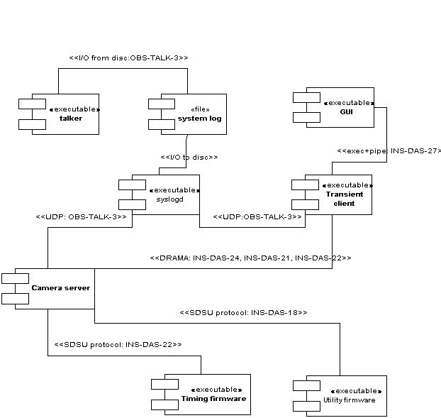
Figure 3.2: principal components in UltraDAS telemetry
This is substantially similar to the case for executing a user command.
The GUI executes a transient-client programme directly; polymorph is
not used. The client in this case remains active indefinitely,
passing the telemetry values to the GUI via a pipe.
The client gets the telemetry from the camera server by monitoring DRAMA parameters in the server. The server gets the telemetry from the embedded programmes by polling. The interfaces here are the same ones used for executing user commands.
Telemetry that cannot be easily expressed as a graphic or text-fragment
on a GUI is written to the system log; this category of "telemetry" includes
all error messages. Text for the log is forwarded either by the client
or, more often, by the server to the syslog daemon. The daemon writes the
text to the log file, and the GUI programme talker displays the log for
the user to see. Talker and syslog are not part of UltraDAS but they must
be present for UltraDAS to function correctly.
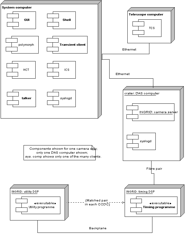
Figure 3.3: deployment of components on processors (preferred)
The system computer and DAS computer are chosen to be SPARCstations. The system computer can be any SPARCstation with sufficient capacity, but Ultra 10s are the preferred machines. The DAS computer must be an Ultra-series machine, and must have the correct expansion bus for the type of camera-interface board in use. Currently, the interface boards are for S-bus, and the DAS computers are Ultra-1s. In due course, the interface boards will be replaced with PCI units and the DAS computers with Ultra-10s.
The timing and utility processors are Motorola DSPs from the 56000 series. The DSPs are integral to the detector controllers and cannot be replaced by the UltraDAS project.
The ICS programmes are generally run on the system computer as this machine has more capcity than is needed for the UIs and client software. The ICS ususally has its own embedded processors beyond the programmes show, but these are far beyond the UltraDAS system-boundary and need not be considered here. The TCS runs on a separate computer as it has great need of capacity and is anyway not portable to Unix.
Figure 3.4 shows an interim arrangement for the WHT where the ICS and the HCT are on a separate computer: a VAX. This allows continued use of the VAX_ADAM ICS, but the arrangement is inconvenient and will be phased out.
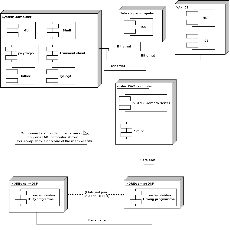
Figure 3.4 deployment of components on processors (WHT, interim).
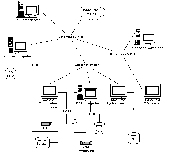
Figure 3.5: network environment.
Notably, the image files have to cross the network several times.
Initially, the observations are written as FITS files on the raw-data discs of the DAS computer. The computer usually has several raw-data discs, but they are normally on the same SCSI chain and are not used in parallel. The speed of the data disc in writing could limit the rate at which the system can takes data. To avoid this, 7200 r.p.m. discs on an Ultra-2 SCSI bus are used, and these write quickly enough that the data-writing time can be hidden inside the readout and processing time of the next observation; the cost is that the camera server has to hold two observations in memory at once.
After observation, the image files are served, via NFS, to the archive computer which parses them to construct the log of observations. This access is entirely asychronous to the recording of new observations, so should not affect the DAS' performance. However, the NFS server on the DAS computer competes for CPU and I/O share with the DAS and can slow it down slightly.
Typically, the observer copies the observation files, via NFS, to the scratch disc on the data-reduction computer, in order to assess the data. This copying again contends with taking of new observations.
During the night, the observer will typically copy observations from the DAS computer to tape. The tape drives are on the data-reduction computer, so the data have to cross the net again.
Finally, the archive computer takes copies of the data at intervals to write to the CD-ROM archive. Again, the data are served via NFS.
So far, the load on the DAS computer due to NFS serving has not been critical. If it becomes so, it might be reduced by serving the data discs to the DAS computer from some central disc-server. However, this would only be viable if the speed of writing to the server equalled or exceeded the speed of writing to the DAS' local discs.
The software for the central intelligence, for the DAS, and for the detector controllers is all served from the system computer by NFS.